3
PANEL DESCRIPTION
3-7
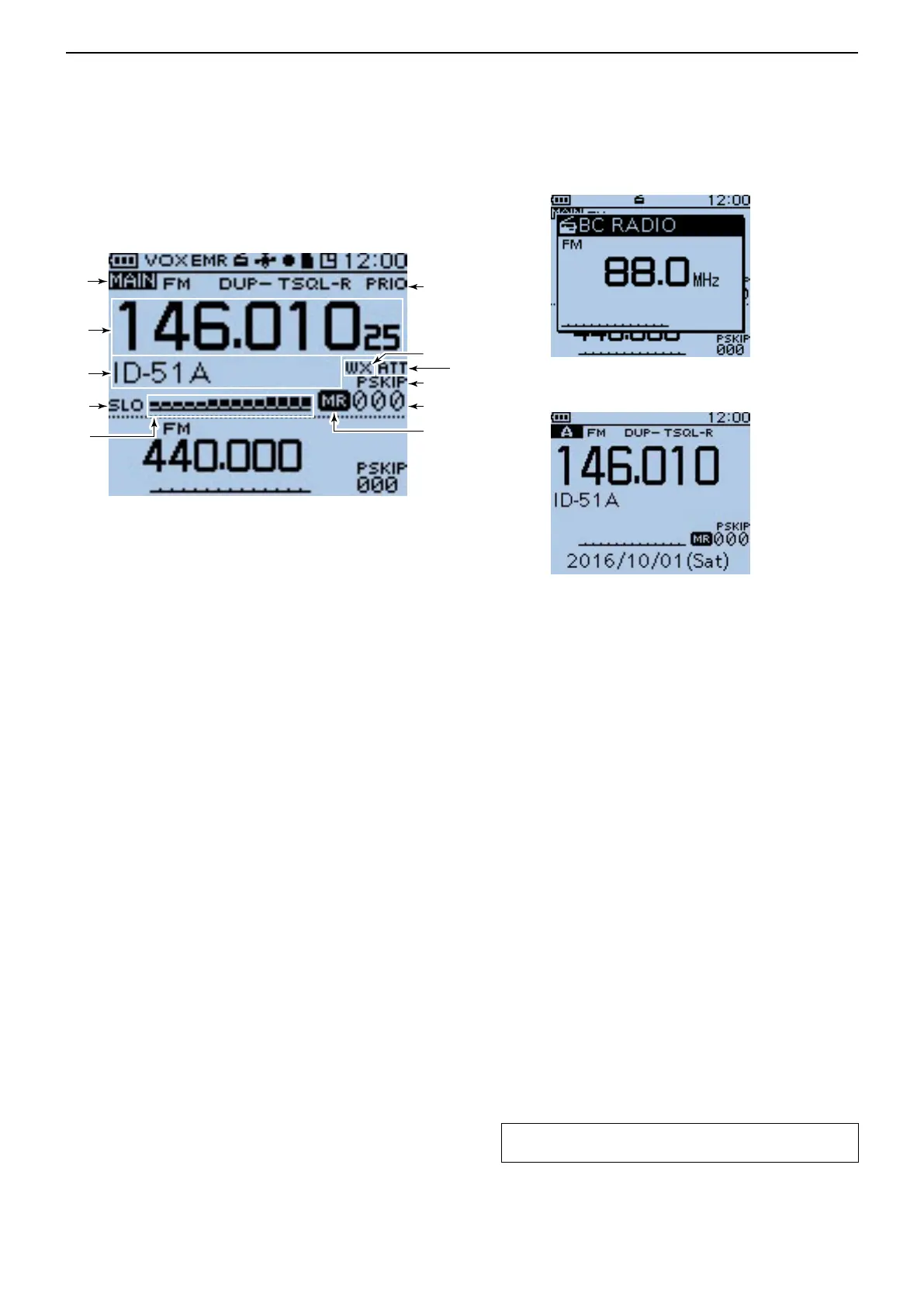
■ Function display (Continued)
Dual band display
Single band display
BC Radio setting pop-up
window (Tuning mode)
!3 PRIORITY WATCH ICON (p. 14-5)
Appears when Priority Watch is in use.
!4 WEATHER ALERT ICON (p. 5-14)
Appears when the Weather alert function is ON.
!5 ATTENUATOR ICON (p. 5-12)
Appears when the attenuator is ON in the AIR band.
!6 SKIP ICON (pp. 13-7, 13-8)
➥ “ SKIP” appears when the selected memory chan-
nel is set as a Skip channel.
➥ “ PSKIP” appears when the displayed frequency
is set as a Skip frequency in the Memory mode.
➥ “ PSKIP” appears while the Frequency Skip Scan
function is ON in the VFO mode.
!7 MEMORY CHANNEL NUMBER
➥ Displays the selected memory channel or bank
number. (p. 12-3)
➥ “C0” to “C3” appears when the Call channel is se-
lected. (p. 12-3)
!8 MEMORY ICON (p. 12-3)
Appears when the Memory mode is selected.
!9 S/RF METER
➥ Shows the relative signal strength of the receive
signal.
➥ Shows the output power level of the transmit signal.
(p. 5-11)
@0 POWER ICONS (p. 5-11)
➥ “ SLO” appears when S-low power is selected.
➥ “ LO1” appears when low 1 power is selected.
➥ “ LO2” appears when low 2 power is selected.
➥ “ MID” appears when mid power is selected.
➥ No icon appears when high power is selected.
@1 MEMORY NAME DISPLAY (p. 12-12)
While in the Memory mode, the programmed mem-
ory or memory bank name is displayed.
@2 FREQUENCY READOUT
Displays a variety of information, such as the operat-
ing frequency, menu contents and so on.
• The decimal point blinks during a scan.
@3 MAIN BAND ICON (p. 5-3)
Shows the selected band (A or B) is the Main band.
➥ Shows the selected band (A or B) is the Main
band.
➥ “ TM” appears while in the Terminal mode.
➥ “ AP” appears while in the Access Point mode.
TIP: See “About the DV Gateway function” that can be
downloaded from the Icom website, for details.
!3
!5
!6
!7
!8
!9
@0
@1
@2
@3
!4
 Loading...


