17
OTHER FUNCTIONS
17-25
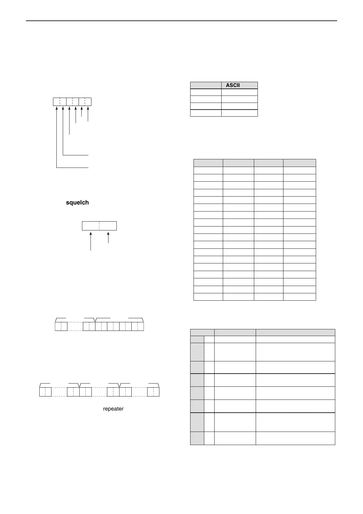
• DTCS code and polarity setting
Command : 1B 02
q
0XXXX
we
X
rt
XX X0
10H zdigit:0, 5
(according to the 100 Hz digit)
1 Hz digit:0
(Fixed)
1 kHz digit:0~9
100 Hz digit:0,2 , 5, 7
100 kHz digit:0~9
10 kHz digit:0~9
10 MHz digit:0~9
1 MHz digit:0~9
1000 MHz digit:0
(Fixed)
100 MHz digit:0~4
00XXXX
q※ we
固定:0
固定:0
100Hz桁
10Hz桁
1Hz桁
0.1Hz桁
XXX0
qw
1kHz桁:0〜3
100Hz桁:0〜9
10Hz桁:0〜9
1Hz桁:0
(固定)
XX0 XXX
q* we
0 (fixed)
First digit: 0~7
Second digit: 0~7
Third digit: 0~7
Receive polarity: 0: Normal
1: Reverse
Transmit polarity: 0: Normal
*See page 16-17 for DTCS code list.
■ CI-V information (Continued)
• DV TX call signs setting (24 characters)
Command : 1F 01
Set “UR,” “R1” and “R2” call signs of 8 characters (fixed).
• • •
XX XXXX X XXX
• • •
• • •
q ~ i: UR (Destination) call sign setting (8 characters)
o ~ !6: R1 (Access/Area repeater) call sign setting
(8 characters)
!7 ~ @4: R2 (Link/Gateway repeater) call sign setting
(8 characters)
• Digital code squelch setting
Command : 1B 07
0~9
0~9
• DV MY call sign setting
Command : 1F 00
Set your own call sign and note of up to 12 characters.
XX
• • •
q ~ i : Your own call sign setting (8 characters)
o ~ !2 : Note setting (4 characters)
• Character’s code of the call sign
Character ASCII code
0 ~ 9 30 ~ 39
A ~ Z 41 ~ 5A
(Space) 20
/ 2F
• DV TX message setting
Command : 1F 02
Set the transmit message of up to 20 characters.
“FF” stops sending or reading messages.
Character ASCII code Character ASCII code
A
~ Z 41 ~ 5A a ~ z 61 ~ 7A
0
~ 9 30 ~ 39 Space 20
! 21 # 23
$ 24 % 25
& 26 \ 5C
? 3F " 22
’ 27 ` 60
^ 5E + 2B
– 2D
✱
2A
⁄ 2F . 2E
, 2C : 3A
; 3B = 3D
< 3C > 3E
(
28
)
29
[
5B
]
5D
{
7B
}
7D
¦
7C
_
5F
¯ 7E @ 40
• DV RX Status setting
Command : 20 0201, 20 0202
Data Function Description
bit7 0 (Fixed) —
bit6 0/1 Receiving a
voice call
While receiving a digital voice
signal, select “1.” (Regardless of
DSQL and CSQL setting)
bit5 0/1 Last call finisher When the last call was finished
by you, select “1.”
bit4 0/1 Receiving a
signal
When the audio tone can be
heard, select “1.”
bit3 0/1 Receiving a BK
call
While receiving a BK call, select
“1.”
bit2 0/1 Receiving a
EMR call
While receiving a EMR call,
select “1.”
bit1 0/1 Receiving a
signal other than
DV
When “DV” and “FM” are blinking,
select “1.”
bit0 0/1 Packet loss
status
While displaying a packet loss.
 Loading...


