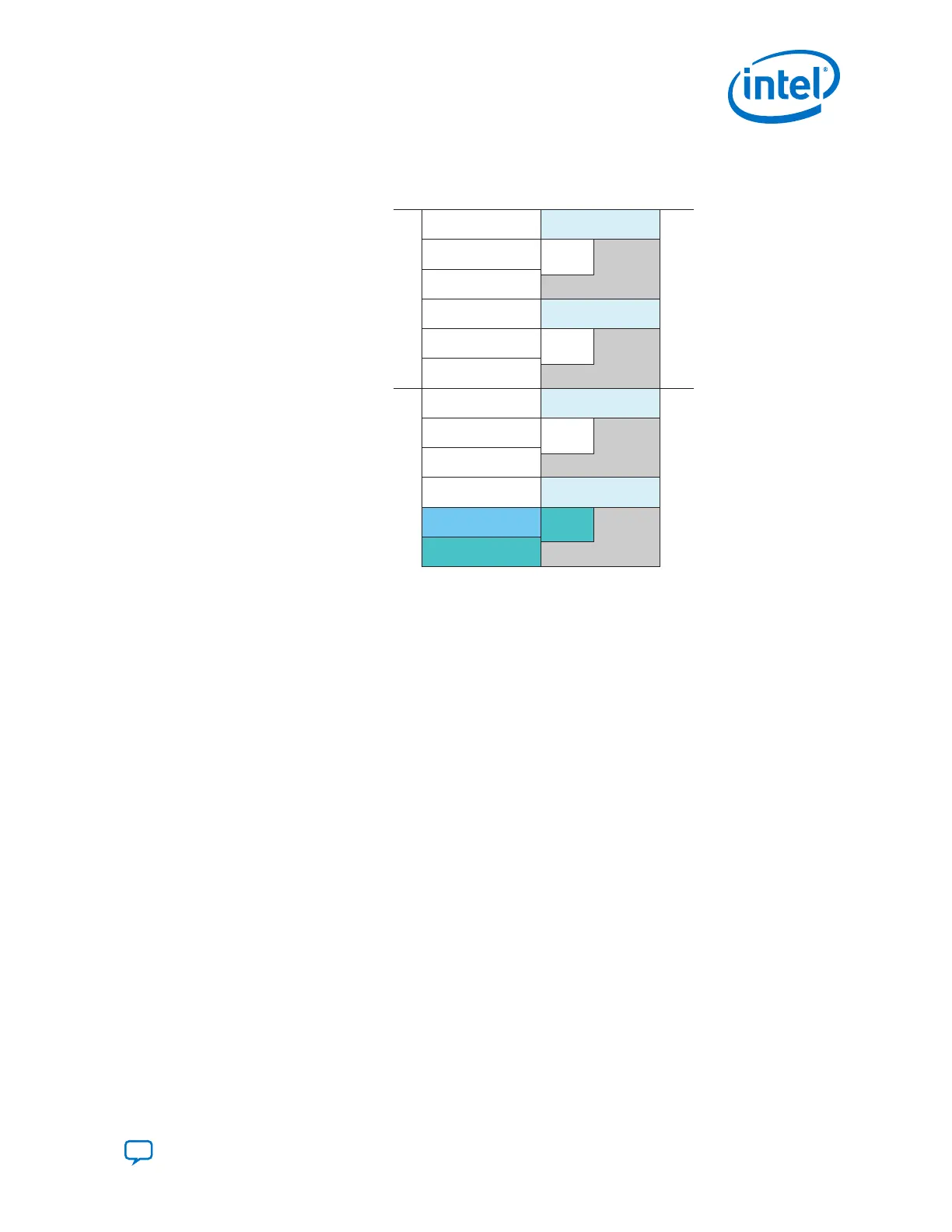
The following figures show the default configurations:
Figure 67. x2 Configuration
CH5
CH4
CH3
CH2
CH1
CH0
CH5
CH4
CH3
CH2
CH1
CH0
Master CH
Data CH
fPLL
ATX
PLL
Master
CGB
fPLL
ATX
PLL
fPLL
ATX
PLL
fPLL
ATX
PLL
Master
CGB
Logical
Channel
Physical
Channel
0
1
Transceiver bank
Transceiver bank
Master
CGB
Master
CGB
Note: The physical channel 0 aligns with logical channel 0. The logical PCS Master Channel 1
is specified as Physical Channel 1.
2. Implementing Protocols in Intel Cyclone 10 GX Transceivers
UG-20070 | 2018.09.24
Send Feedback
Intel
®
Cyclone
®
10 GX Transceiver PHY User Guide
147