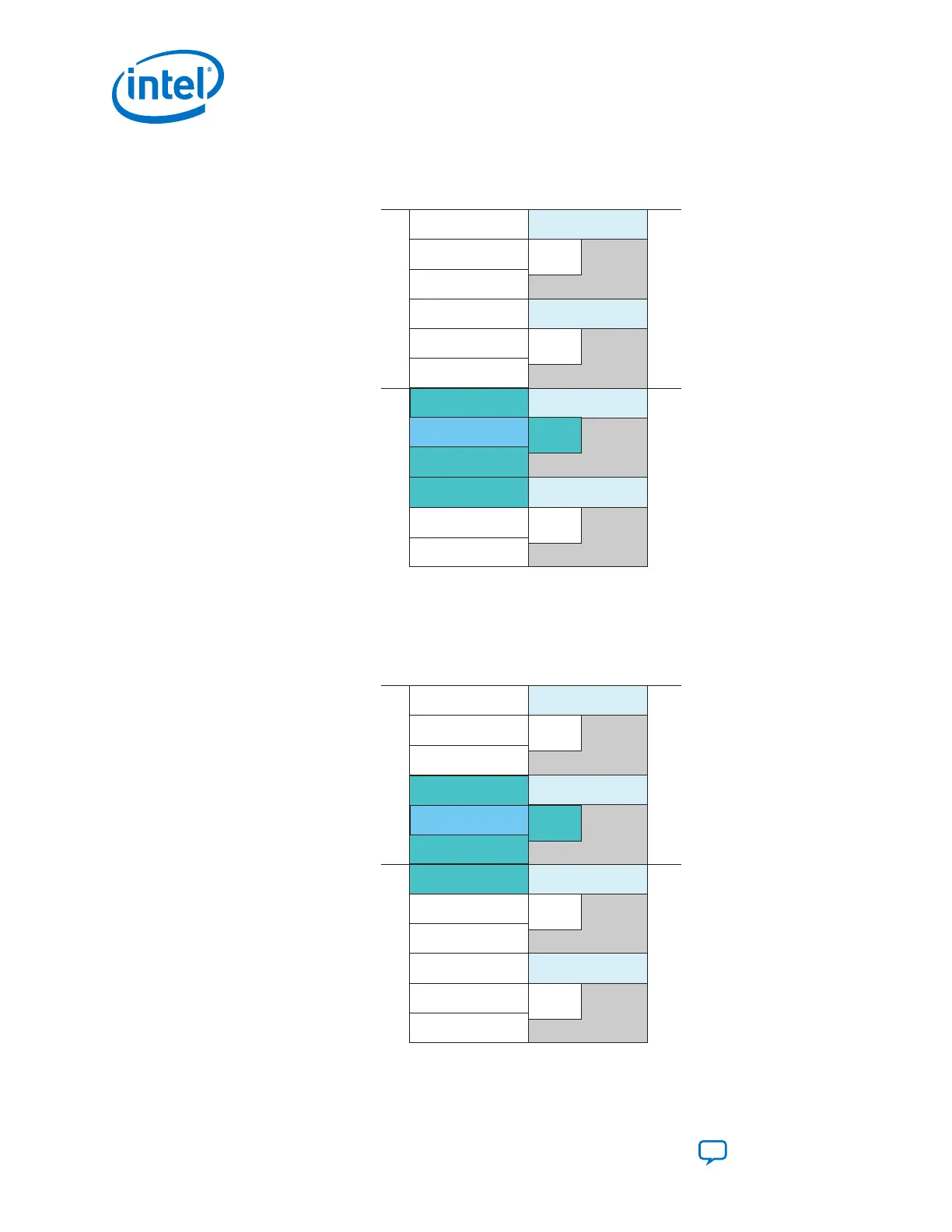
Figure 68. x4 Configuration
The figure below shows an alternate way of placing 4 bonded channels. In this case, the logical PCS Master
Channel number 2 must be specified as Physical channel 4.
CH5
CH4
CH3
CH2
CH1
CH0
CH5
CH4
CH3
CH2
CH1
CH0
Data CH
fPLL
ATX
PLL
fPLL
ATX
PLL
fPLL
ATX
PLL
fPLL
ATX
PLL
Logical
Channel
Physical
Channel
0
1
Transceiver bank
Transceiver bank
2
3
Data CH
Master
CGB
Master
CGB
Master CH
Master
CGB
Master
CGB
Data CH
Figure 69. x4 Alternate Configuration
The figure below shows an alternate way of placing 4 bonded channels. In this case, the logical PCS Master
Channel number 2 must be specified as Physical channel 1.
CH5
CH4
CH3
CH2
CH1
CH0
CH5
CH4
CH3
CH2
CH1
CH0
Master CH
fPLL
ATX
PLL
fPLL
ATX
PLL
fPLL
ATX
PLL
fPLL
ATX
PLL
Logical
Channel
Physical
Channel
0
1
Transceiver bank
2
3
Data CH
Data CH
Master
CGB
Master
CGB
Transceiver bank
Data CH
Master
CGB
Master
CGB
2. Implementing Protocols in Intel Cyclone 10 GX Transceivers
UG-20070 | 2018.09.24
Intel
®
Cyclone
®
10 GX Transceiver PHY User Guide
Send Feedback
148