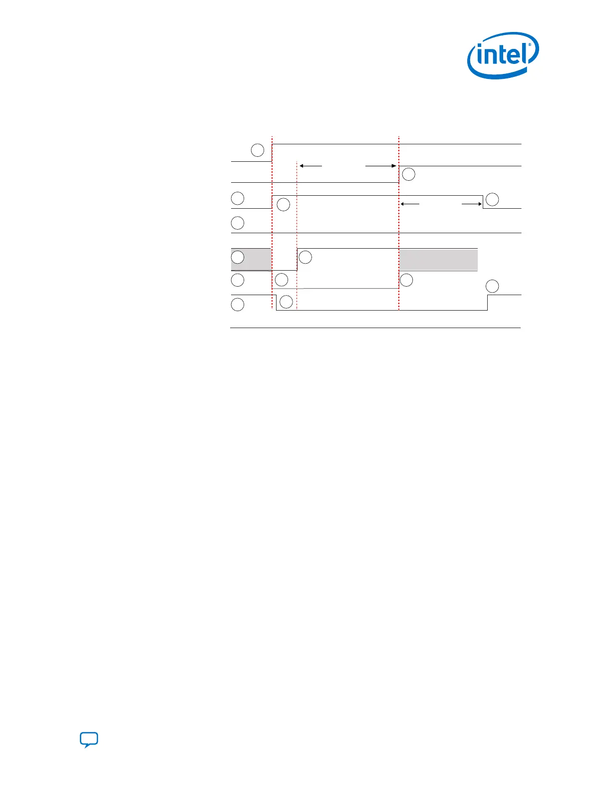
Figure 151. Reset Sequence Timing Diagram for Receiver when CDR is in Manual Lock
Mode
rx_digitalreset
rx_set_locktoref
rx_set_locktodata
rx_is_lockedtoref
rx_is_lockedtodata
rx_analogreset
rx_ready
Status Signals
Control Signals
1
2
2
4
5
6
3
1
1
1
1
2
4
4
rx_cal_busy
LTD_Manual
t
LTD_Manual
t
4.3.1.1.3. Resetting the Transceiver Channel During Device Operation
The numbers in this list correspond to the numbers in the following figure.
1.
Assert tx_analogreset, pll_powerdown, tx_digitalreset,
rx_analogreset, and rx_digitalreset. Ensure that pll_cal_busy,
tx_cal_busy, and rx_cal_busy are low.
2.
Deassert pll_powerdown and tx_analogreset at the same time, after a
minimum duration of 70 μs.
3.
The pll_locked signal goes high after the TX PLL acquires lock. Wait for a
minimum 70 μs after deasserting tx_analogreset to monitor the pll_locked
signal.
4.
Deassert tx_digitalreset after pll_locked goes high. The
tx_digitalreset signal must stay asserted for a minimum t
tx_digitalreset
(minimum of 70 μs) duration after tx_analogreset is deasserted.
5.
Deassert rx_analogreset after deasserting tx_analogreset.
6.
Ensure rx_is_lockedtodata is asserted for t
LTD
(minimum of 4 μs) before
deasserting rx_digitalreset.
4. Resetting Transceiver Channels
UG-20070 | 2018.09.24
Send Feedback
Intel
®
Cyclone
®
10 GX Transceiver PHY User Guide
251