MAINTENANCE AND SERVICING
NOTE:
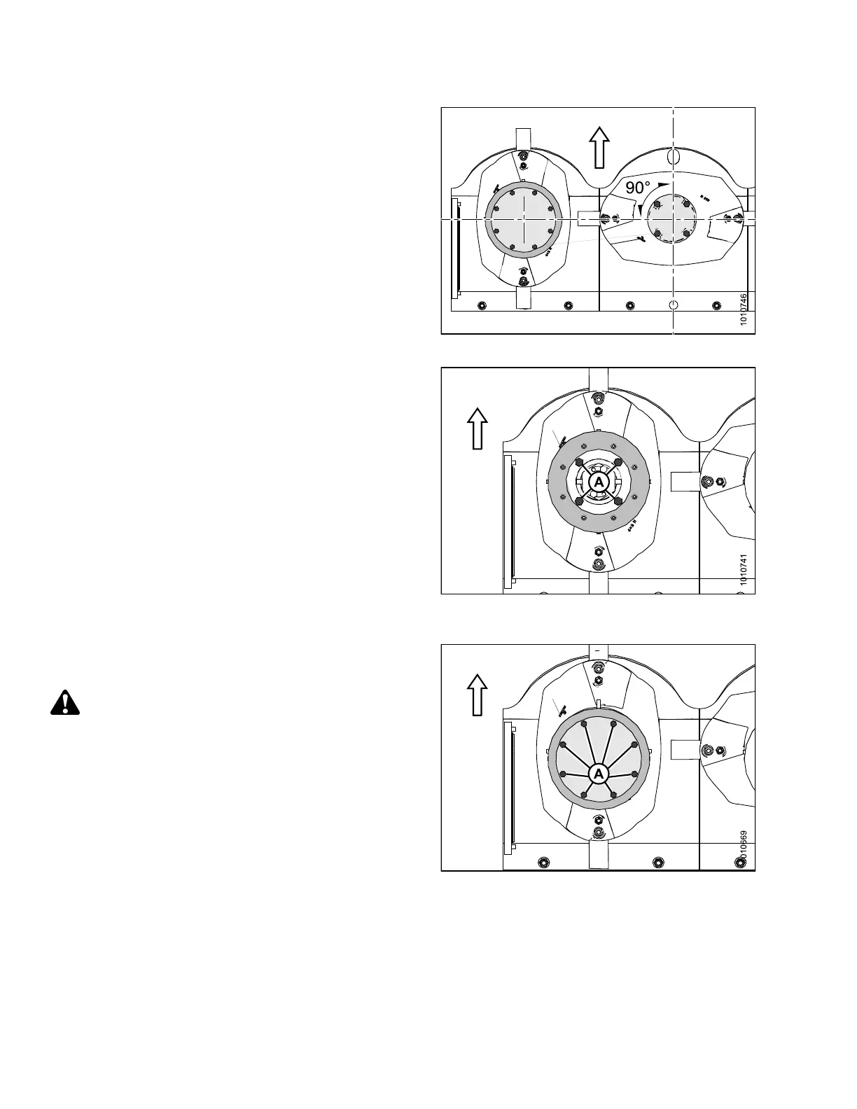
Arrow indicates forward direction.
1. Orient each disc at a 90 d egree angle relative to the
neighborin g discs.
NOTE:
Discs are dir
ection-s pecific. It is important to ensure
proper disc o
rientation.
Figure 4.121: Cutterbar Discs (Top View)
2. Position the non-driven rotary deflector.
3. Use a 12 in. (305 mm) extension and 16 mm deep
socket to install the four M10 bolts (A) and washers
that hold the defle c to r disc in place. Torque to
40 ft·lbf (55 N·m).
Figure 4.122: Non-Driven Rotary Deflector
(Top View)
4. Install eight M8 bolts (A) and washers to secure the
cover to the non-driven rotary deflector, and torque to
20 ft·lbf (28 N·m).
WARNI
NG
Ensure cutterbar is completely clear of foreign
objects. Foreign objects can be ejected with
considerable force when the machine is started and
may result in serious injury or machine damage.
Figure 4.123: 16-Foot Mower
Conditioner Shown
147910
17
4
Revision A