REFERENCE
7.2.3 M etric B
olt Specifi cations Bolting into Cast Alum inum
Table 7.10 Metric Bolt Bolting into Cast Aluminum
Bolt Torque
8.8
(Cast Alumin
um)
10.9
(Cast Alumin
um)
Nominal
Size (A)
ft·lbf
N·m
ft·lbf
N·m
M3
––
1
–
M4
––
2.6 4
M5
––
5.5
8
M6 6 9 9 12
M8 14 20 20 28
M10 28 40 40
55
M12 52 70 73 100
M14
––––
M16
––––
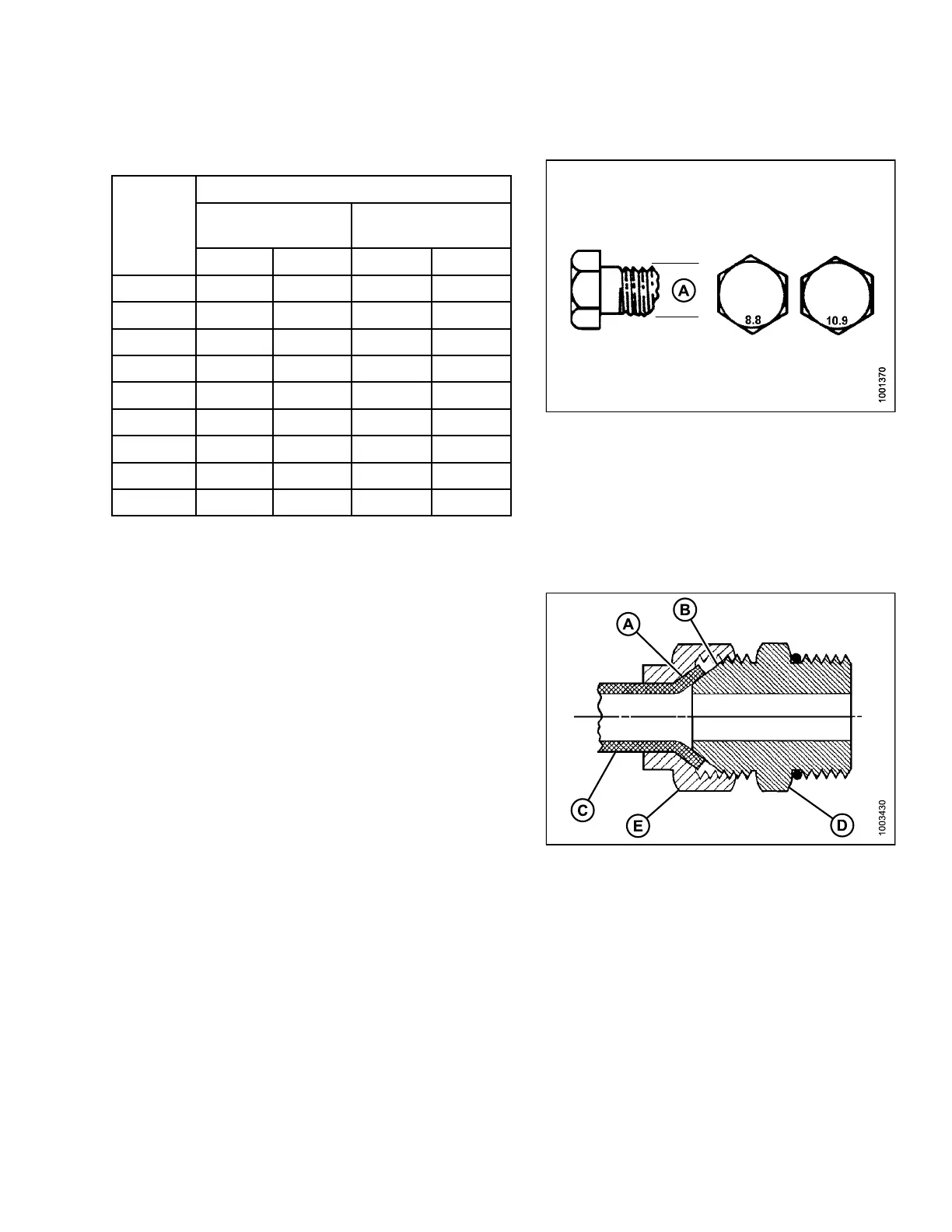
Figure 7.9: Bolt Grades
7.2.4 Flare-Type Hydraulic Fittings
1. Check flare (A) and flare seat (B) for defects that might
cause leakage.
2. Align tube (C) with fitting (D) and thread nut (E) onto
fitting without lubrication until contact has been made
between the flared surfaces.
3. Torque the fitting nut (E) to the specified number of
flats from finger tight (FFFT) or to a given torque value
in Table 7.11 Flare-Type Hydraulic Tube Fittings, page
266.
4. Use two wrenches to prevent fit ting (D) from rota ting.
Place one wrench on the fitting body (D) and tighten
nut (E) with the other wrench to the torque shown.
5. Assess the final condition of the connection.
Figure 7.10
: Hydraulic Fitting
147910 265 Revision A