MAINTENANCE AND SERVICING
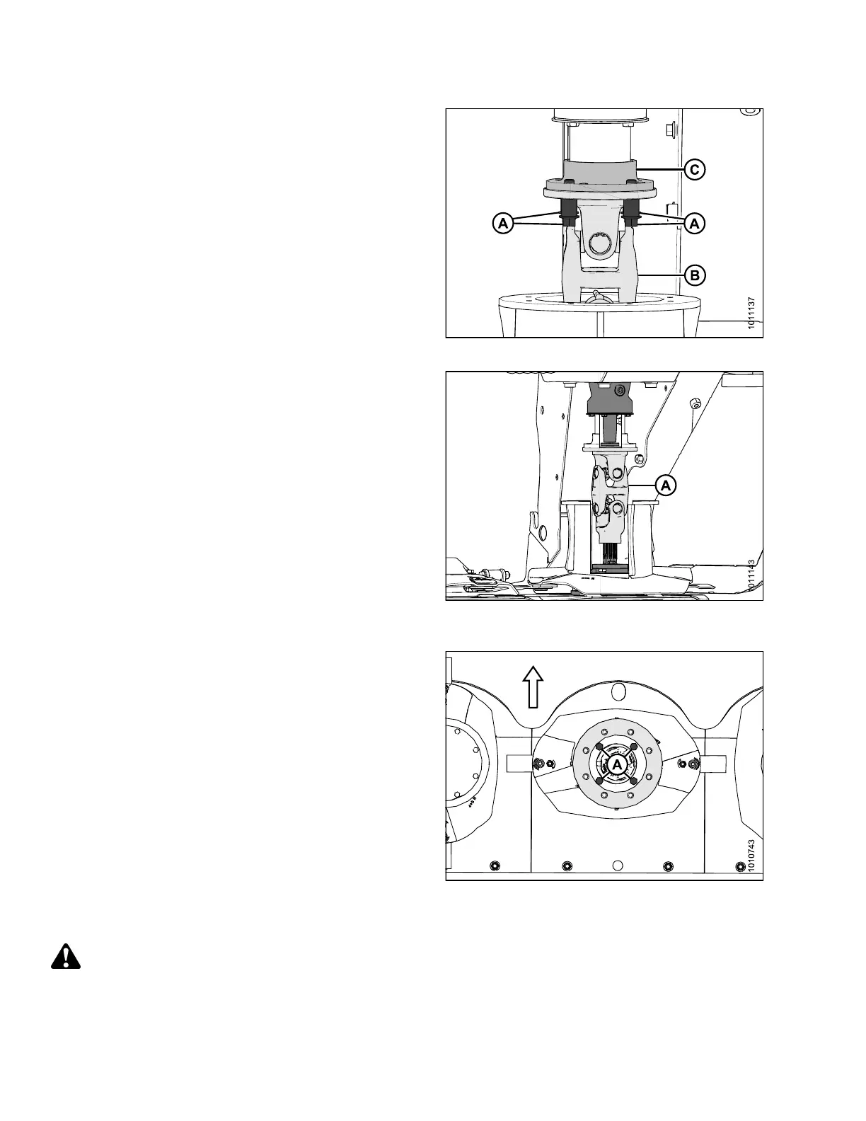
7. Remove four M12 hex flange head bolts (A) and
spacers securing driveline assembly (B) t o hub
drive (C).
Figure 4.106: Driveline Hardware
8. Slide driveline (A) downwards, tilt to the side, and pull
driveline up and out of drum (cutaway view of drum and
tube shield shown for improved clarity).
Figure 4.107: Vertical Driveline (Cutaway
View Shown)
9. Look down into the rotary deflector, and use a
12 in . (305 mm) extension and 1 6 mm deep socket to
remove the four M12 bolts (A) and washers holding
the deflector disc in place.
10. Remove deflector disc assem bly.
Figure 4.108: Driven Rotary Deflector (Top View)
Installing Driven Rotary Deflectors and Driveline
DANGER
To avoid bodily injury or death from unexpected start-up or fall of a raised machine, stop engine, remove
key, and engage header lift cylinder lock-out valves before going under machine for any reason.
147910 168 Revision A