MAINTENANCE AND SERVICING
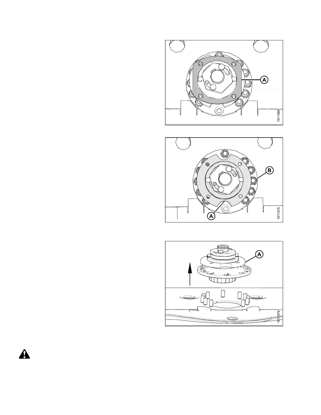
7. Remove spacer plate (A).
Figure 4.34: Spacer Plate
8. Rotate spindle hub (A) to access nuts, and remove 11
M12 lock nuts (B) and washers.
Figure 4.35: Left-Hand Spindle Hub
and Hardware
9. Remove spindle (A) from cutterbar.
Figure 4.36: Left-Hand Spindle
Installing Cutterbar Spindles
DANGER
To avoid bodily injury or death from unexpected start-up or fall of a raised machine, stop engine, remove
key, and engage header lift cylinder lock-out valves before going under machine for any reason.
147910 136 Revision A