MAINTENANCE AND SERVICING
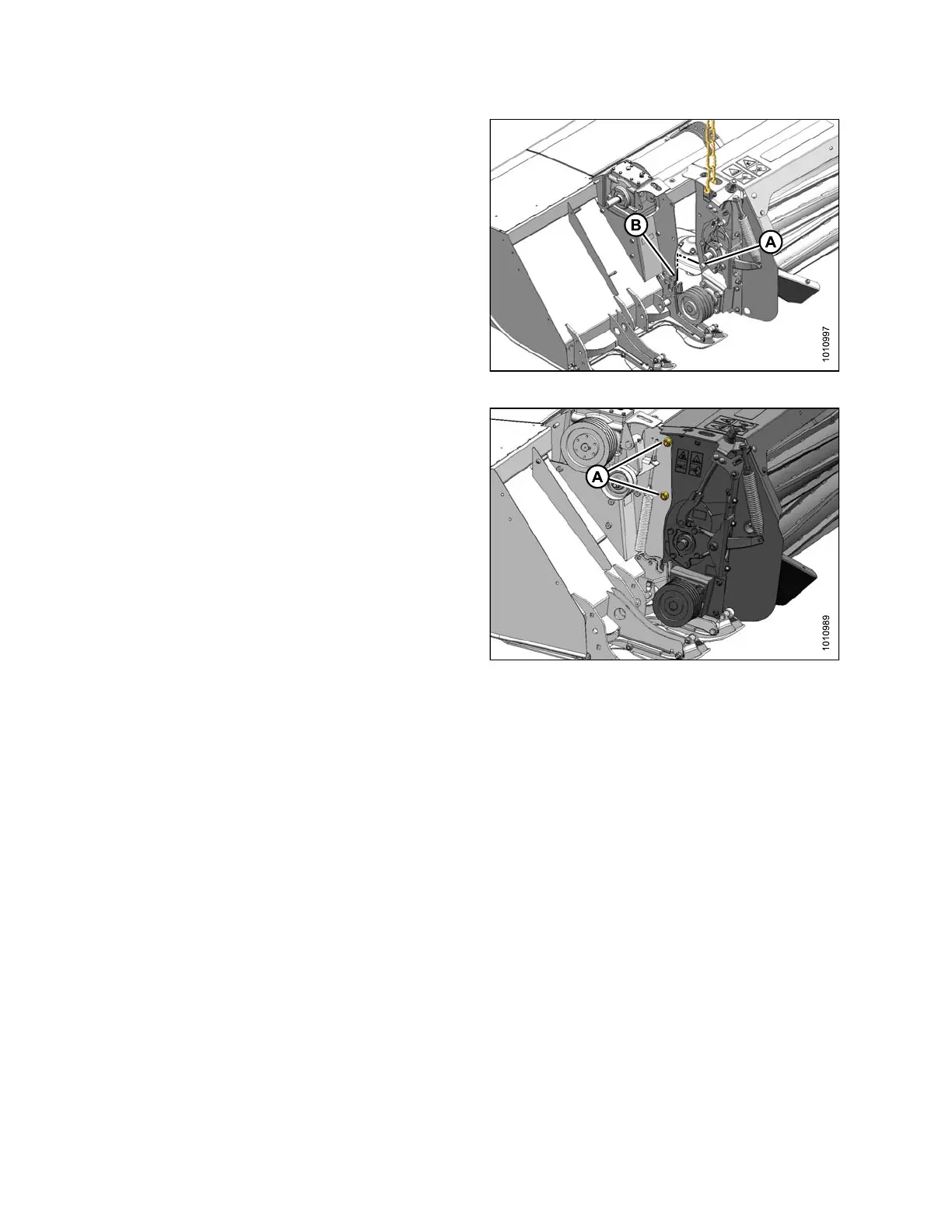
3. Carefully align pin (A) at each end of conditioner with
lug (B) on mower, and lower conditioner so that pins (A)
engage lugs (B) on mower.
Figure 4.274: Conditioner Pins
4. Align mounting holes and install four M16 x 40 hex
head bolts (A) with heads facing inboard (two per side).
Secure with M16 center lock flanged nuts and torque
to 126 ft·lbf (1 70 N·m).
5. Remove lifting chains from conditioner and move lifting
device clear of w ork area.
6. If necessary, install conditioner drive components.
Refer to Installing C onditioner D rive, page 2 38.
Figure 4.275: Left Side of Conditioner –
Right Side Si m ilar
Installing Conditioner Drive
This p
rocedure describes the installation of the conditioner drive components on a machine that was originally
supp
lied with no conditioner.
1. Retr
ieve bag of following parts from conditioner
ship
ment:
•Shaftkey
• Pulley
• Bushing with three M10 bolts
• Tensioner assem bly
• M16 Hex head bolt
• M16 nut
• Two M10 nuts
• Eye bolt
• Hardened washer
•Spring
147910 238 Revision A