MAINTENANCE AND SERVICING
4.4.3 Cutterb
ar Spindles
Discs are factory installed to produce a three crop stream, but disc rotation patterns can be changed to suit
crop conditions.
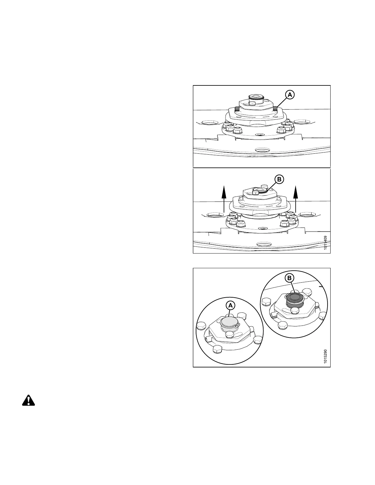
To prevent damage to the cutterbar and drive systems,
each disc is attached to a spindle containing a shear
pin (A). If the disc contacts a large object such as a stone
or stump , the pins will shear and the disc will sto p rotating
and move upwards wh ile remaining attached to the spindle
with a snap ring (B). Refer to 4.4.11 Cutt erba r S pindle
Shear Pin, page 175 to replace shear pin.
Figure 4.29: Cutterbar Spindles
IMPORTANT:
• Spindles that rotate clockwise have
right-handed threading and a smooth top on the
spindle gear shaft (A).
• Spindles that rotate counterclockwise have left-handed
threading and machined grooves on the spindle gear
shaft (B).
Figure 4.30: Cutterbar Spindles
Removing Cutterbar Spindles
DANGER
To avoid bodily injury or death from unexpected start-up or fall of a raised machine, stop engine, remove
key, and engage header lift cylinder lock-out valves before going under machine for any reason.
147910 134 Revision A