REFERENCE
7.2.6 O -Ring B
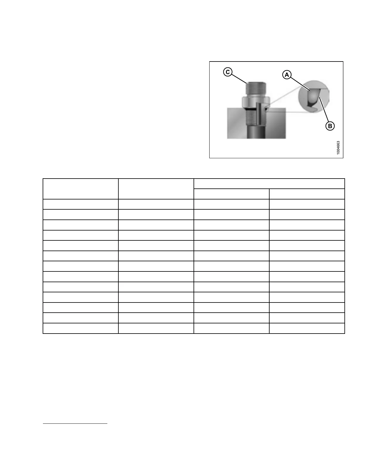
oss (ORB) Hydraulic Fittings (Non-Adjustable)
1. Inspect O-ring (A) and seat (B) for dirt or
obvious defects.
2. Check that O-ring (A) is NOT on the threads and adjust
if necessary.
3. Apply hydraulic system oil to the O-ring.
4. Install fitting (C) into port until fitting is hand tig ht.
5. Torque fitting (C) according to the values in
Table 7.13 O-Ring Boss (ORB) Hydraulic Fittings
(Non-Adjustable), page 269.
6. Check the final condition of the fitting.
Figure 7.13: Hydraulic Fitting
Table 7.13 O-Ring Boss (ORB) Hydraulic Fittings (Non-Adjustable)
Torque Value
11
SAE Dash Size Thread Size (in.)
ft·lbf (*in·lbf) N·m
-2 5/16–24 *53–62 6–7
-3 3/8–24 *106–115 12–13
-4 7/16–20 14–15 19–21
-5 1/2–2
0
15–24 21–33
-6 9/16–18 19–21 26–29
-8 3/4–16 34–37 46–50
-10 7/8
–14
55–
60
75–
82
-12 1-1/16–12 88–97 120–132
-14 1-3/8–12 113–124 153–168
-
16
1
-5/16–12
1
30–142
1
76–193
-20 1-5/8–12 163–179 221–243
-24 1-7/8–12 199–220 270–298
-32 2-1/2–12 245–269 332–365
11. Torque values shown are based on lubricated connections as in reassembly.
147910 269 Revision A