MAINTENANCE AND SERVICING
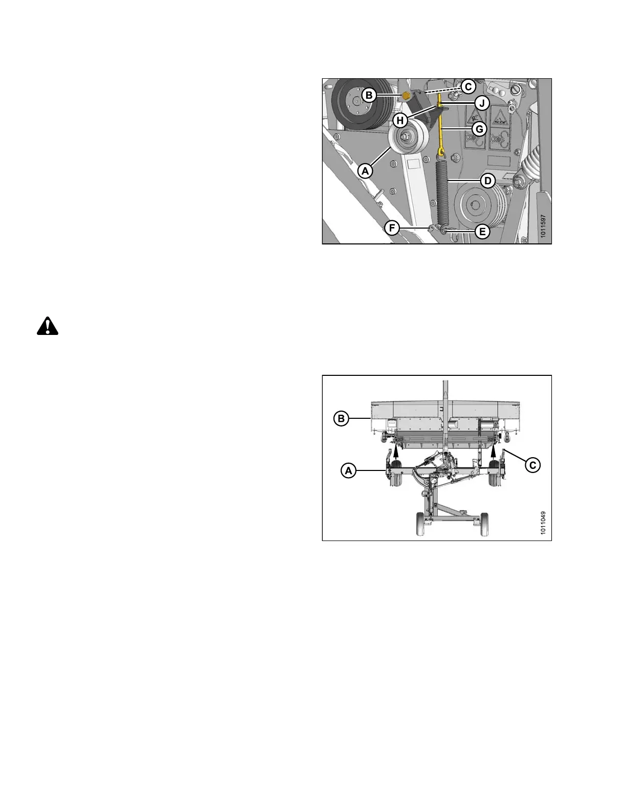
6. Position tensioner assembly (A) as shown and secure
with M16 x 120 bolt (B) and nut (C). Torque nut to
35-40 ft·lbf (47 -54 N·m).
7. Install spring (D) onto frame [rear hole (E) for finger
conditioner, forward hole (F) for roll conditioner].
8. Install eyebolt (G) onto tensioner (A) and spring (D).
Secure eyebolt with hardened washer (H) and two M10
nuts (J).
NOTE:
Conditioner drive belt will be installed after the ca rrier
and header are re-attached.
Figure 4.279: Tensioner
Assembling Header and Carrier
The carri
er must be attached to a tractor for the header and carrier to be assembled.
DANGER
To avoid bodily injury or death from unexpected startup of machine, always stop engine and remove key
from ignition before leaving operator ’s seat for any reason.
1. Start tractor and maneuver carrier (A) directly behind
the mower conditioner (B) so carrier legs line up with
the header attachment points.
2. Drive slowly forward to engage the carrier legs (C) into
the header attachment brackets.
Figure 4.280: Carrier Aligned with
Mower C onditioner
147910 240 Revision A