MAINTENANCE AN D SERVICING
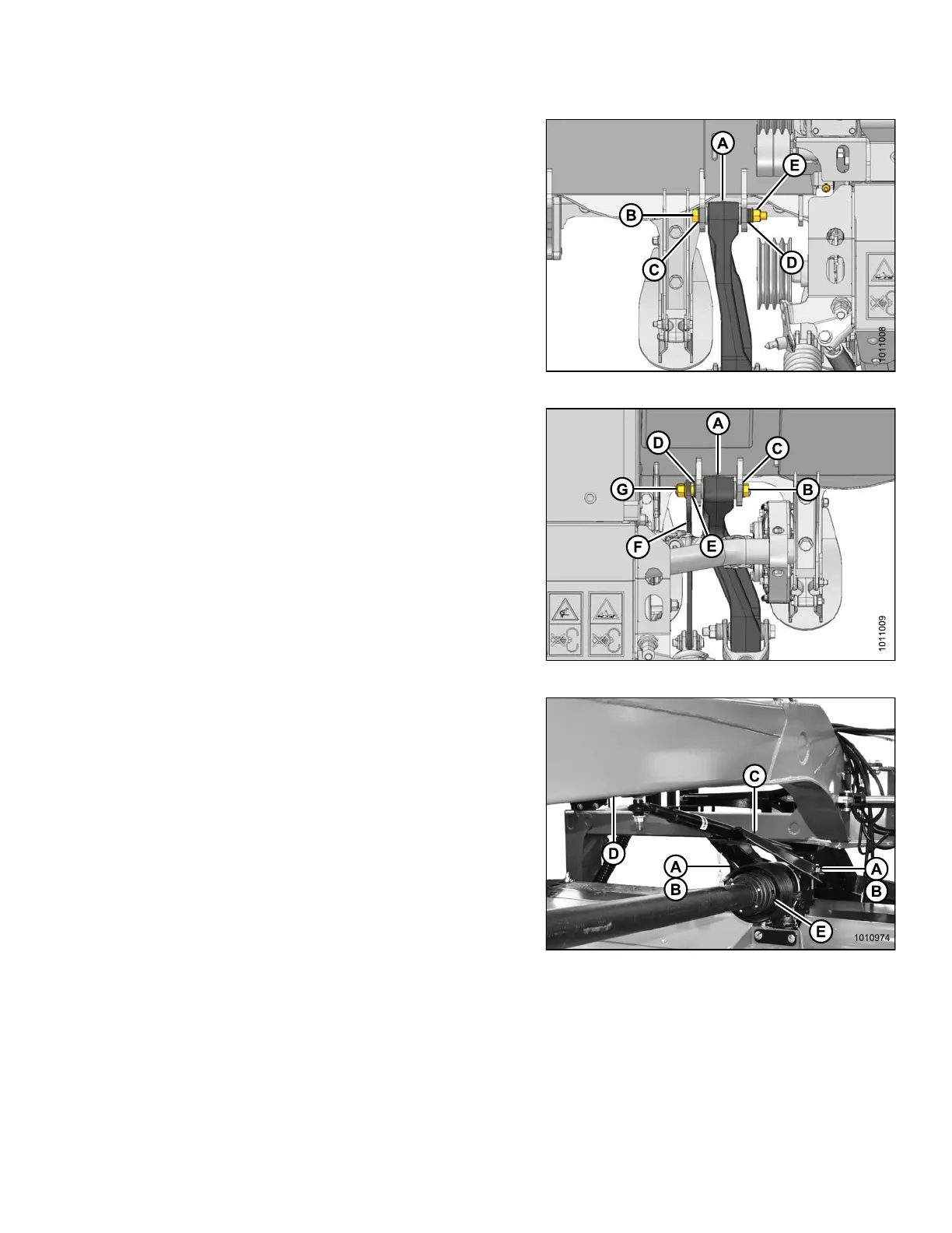
3. Inspect carrier leg (A) for excess gap between inner
steel sleeve of the bushing and the header brackets.
If there is a gap, install washer (MD #5113, 0.047 in.
[1.2 mm thick]) to both sides of the carrier leg to
minimize the gap.
4. Align left side carrier leg (A) with header brackets, and
install M 20 x 40 bolt (B) with hardened washer (C).
5. Install three hardened washers (D) and flanged lock
nut (E) on bo lt (B).
6. Torque bolt (B) to 250 ft·lbf (339 N·m).
Figure 4.281: Left Leg
7. Inspect carrier leg (A) for excess gap between inner
steel sleeve of the bushing and the header brackets.
If there is a gap, install washer (MD #5113, 0.047 in
[1.2 mm thick]) to both sides of the carrier leg to
minimize the gap.
8. Align right side carrier leg (A) with header brackets, and
install M 20 x 40 bolt (B) with hardened washer (C).
9. Install hardened washer (D), spacer (E), float tension
arm (F), and flanged lock nut (G) on bolt (B).
10. Torque bolt (B) to 250 ft·lbf (339 N·m).
Figure 4.282: Right Leg
11. Undo strapping or wire supporting driveline to hitch (D),
and connect driveline (E) to header drive gearbox.
Refer to Installing Clutch Driveline, page 194.
12. Remove hex head bolts (A) and spacers (B)
from gearbox.
13. Undo strapping or wire supporting steering arm
to hitch, and position steering a rm weldment (C)
on gearbox.
14. Secure steering arm to gearbox with spacers (B) and
hex head bolts (A). Apply red Loctite
®
to front holes and
torque bolts to 150 ft·lbf (203 N·m).
Figure 4.283: Aft Driveline and Steering Arm
147910
24
1
Revision A