MAINTENANCE AND SERVICING
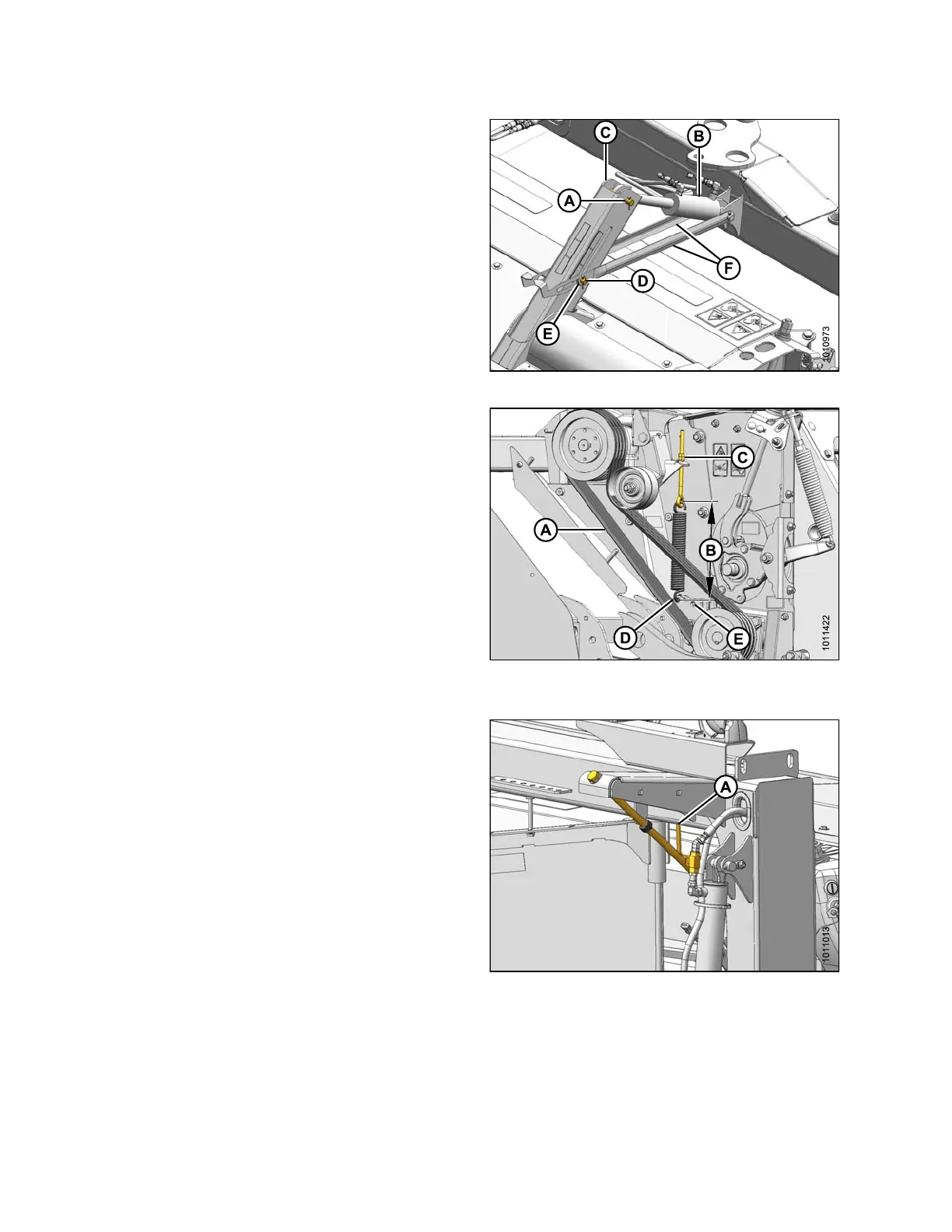
15. Undo strapping or wire securing center-link (B) and
indicator links (F) to carrier frame.
16. Remove pins and hardware from anchor (C).
17. Attach center-link (B) to anchor (C) with clevis pin (A)
andsecurewithcotterpin.
18. Attach indicator links (F) to anch or w ith clevis p in (D)
and was hers (E). Inst all washe rs (E) on both sides of
each indicator link (F).
Figure 4.284: Center-Link and Indicator Links
NOTE:
Ensure proper pulley configuration insta llat ion—large
pulley installed onto gearbox for roll conditioner,
and small pulley installed onto gearb ox for
finger conditioner.
19. Install c
onditioner drive belts (A) onto pulleys.
20. Check th
at ten sioner s pring is installed at
correct
location:
• Hole (D) for roll conditioner
•Hole(E)forfinger conditioner
21. Tighten idler tensioner nut (C) until spring length (B)
measures 14-3/8 in. (365 mm).
22. Tighten jam nut.
Figure 4.285: Conditioner Drive
23. Check that lift cylinder lock-out valves (A) are open.
24. Start tractor and fully raise header.
25. Shut down tractor and remove key from ignition.
Figure 4.2
86: Lift Cylinder Lock-Out Valve
147910
24
2
Revision A