MAINTENANCE AND SERVICING
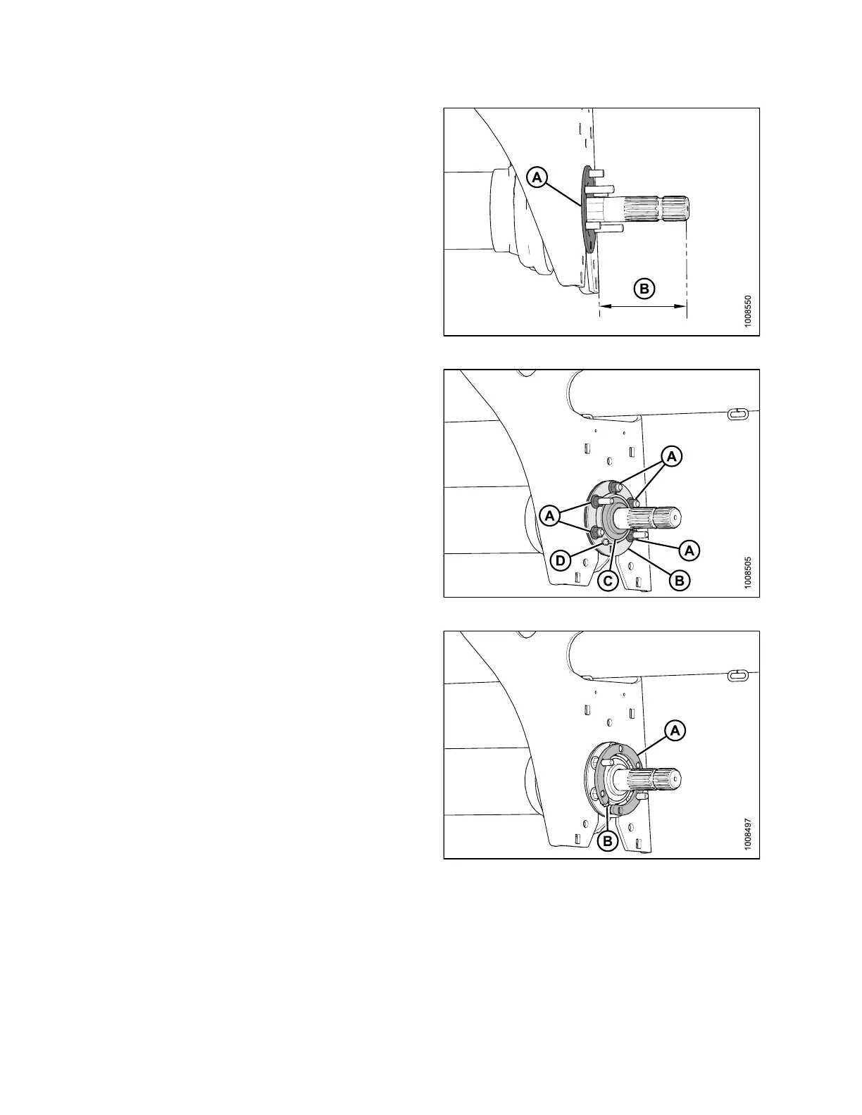
6. Install flange (A).
7. Ensure distance (B) between the tip of the shaft and the
front face of the center support is 5-1/2 in. (+/- 5/32 in.)
(140 mm [+/- 4 mm]).
Figure 4.162: Flange Installed at Center Support
8. Install the ball bearing (C).
9. Tighten the locking collar in the direction of the shaft
rotation.
10. Install flange (B) with grease fitting (D), and five
nuts (A).
IMPORTANT:
Grease fitting (D) must be positioned 90 degrees
from long bolts as shown.
Figure 4.163: Flange
11. Insta ll spac er (A) with cutout in spacer aligned with
grease fitting (B).
Figure 4.164: Spacer Installed at Center Support
147910 190 Revision A