MAINTENANCE AND SERVICING
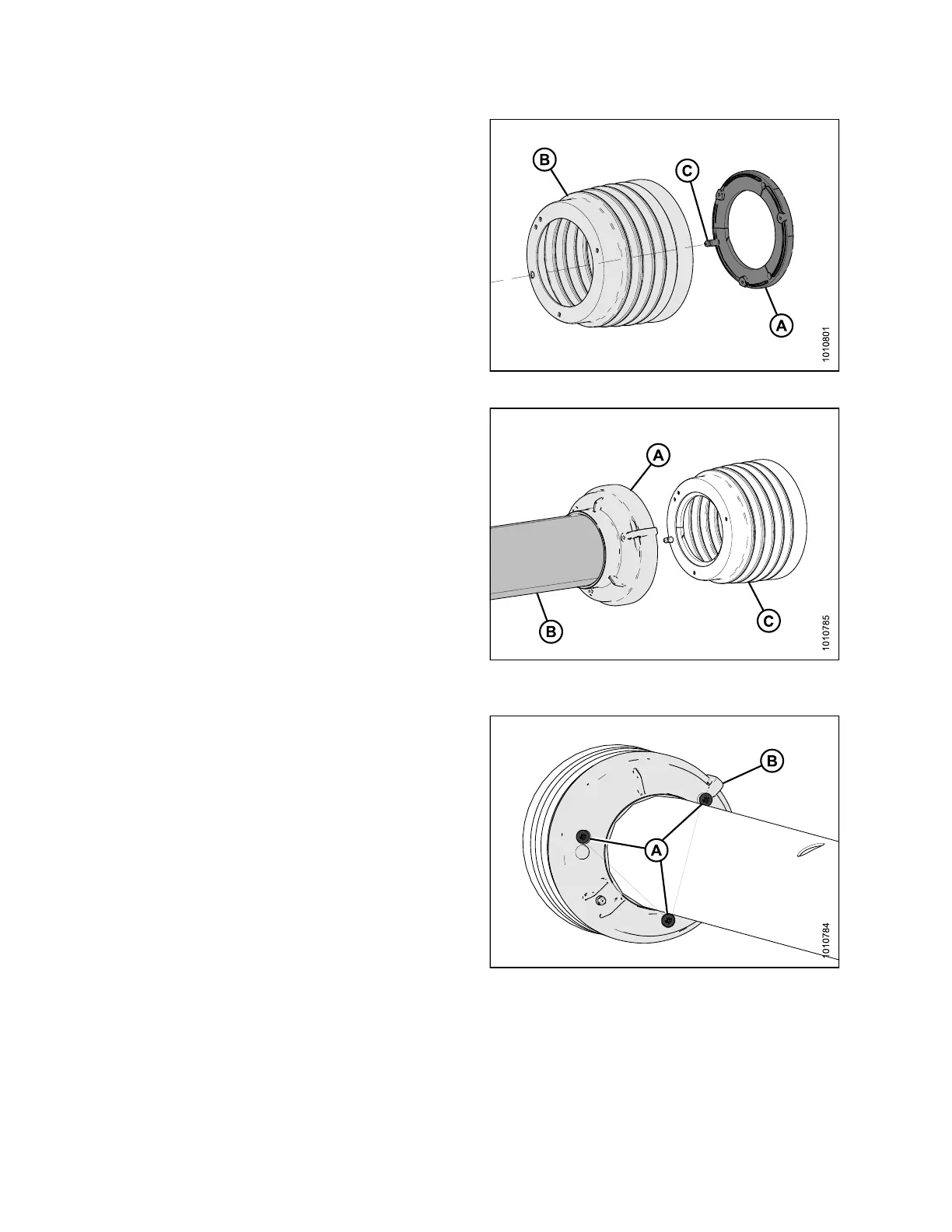
4. Install shield support (A) into outer cone (B), and
ensure that grease fitting (C) is inserte d in to th e
proper hole.
Figure 4.193: Shield Support and Outer Cone
5. Attach th e base cone (A) and shield tube (B) to the
outer cone (C).
Figure 4.194: Base Cone, Shield Tube, and
Outer Cone
6. Install three self-tappin g Phillips head screw s (A) into
base cone (B).
NOTE:
Hand-t
ighten only using an appropriate screw driver.
Do NOT
use a powered tool to tighten screws.
Figure 4 .195: Phillips Hea d Screws Ins talled in
Base Cone
147910 204 Revision A