F1–34
CONTROL SYSTEM
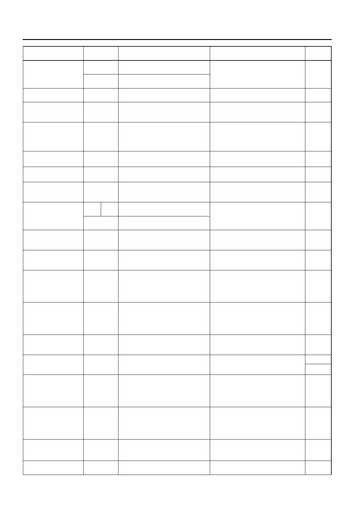
BARO*
7
(Barometric pressure)
kPa, inHg
Ignition switch ON (at sea level):
approx. 101 kPa {29.8 inHg}
Inspect BARO sensor. 1G
V
Ignition switch ON (at sea level):
approx. 4.1 V
BOO
(Brake switch)
ON/OFF
Brake pedal depressed: ON
Brake pedal released: OFF
Inspect brake switch. 1K
CHRGLP (Generator
warning light)
ON/OFF
Ignition switch ON: ON
Idle: OFF
Perform applicable DTC
troubleshooting.
(See F1–54 DTC TABLE)
—
COLP*
4
(Refrigerant
pressure switch
(middle))
ON/OFF
Refrigerant pressure switch (middle)
ON
*2
at idle: ON
Refrigerant pressure switch (middle)
OFF
*3
at idle: OFF
Inspect refrigerant pressure switch. 1Q
CPP*
8
(Clutch pedal position)
ON/OFF
Clutch pedal depressed: ON
Clutch pedal released: OFF
Inspect clutch switch. 1R
CPP/PNP*
8
(Shift
lever position)
Drive/
Neutral
Neutral position: Neutral
Others: Drive
Inspect neutral switch. 1W
DTCCNT (Number of
DTC detected)
——
Perform applicable DTC
troubleshooting.
(See F1–54 DTC TABLE)
—
ECT (Engine coolant
temperature)
°C °F
ECT 20 °C {68 °F}: 20 °C {68 °F}
ECT 60 °C {140 °F}: 60 °C {140 °F}
Inspect ECT sensor. 1M
V
ECT 20 °C {68 °F}: 3.04—3.14 V
ECT 60 °C {140 °F}: 1.29—1.39 V
EVAPCP (Purge
solenoid valve duty
value)
%
Ignition switch ON: 0%
Idle: 0%
Inspect following PIDs: IAT, RPM,
ECT, MAF, O2S11,BARO, INGEAR,
TR, VPWR.
4U
FAN1
(Cooling fan control)
ON/OFF
ECT below 100 °C {212 °F}: OFF
Others: ON
Inspect following PIDs: RPM, TP,
ECT, ACSW, COLP, TEST.
Inspect cooling fan relay.
4L
FAN2
(Cooling fan control)
ON/OFF
ECT below 108 °C {226 °F}: OFF
A/C operating, refrigerant pressure
switch (middle) is OFF, and ECT
below 108 °C {226 °F}: OFF
Others: ON
Inspect following PIDs: RPM, TP,
ECT, ACSW, COLP, TEST.
Inspect cooling fan relay.
4F
FAN3
(Cooling fan control)
ON/OFF
ECT below 100 °C {212 °F}: OFF
A/C operating, refrigerant pressure
switch (middle) is ON, and ECT
below 108 °C {226 °F}: OFF
Other: ON
Inspect following PIDs: RPM, TP,
ECT, ACSW, COLP, TEST.
Inspect cooling fan relay.
4B
FDPDTC
(Pending code caused
FFD storage)
——
Perform applicable DTC
troubleshooting.
(See F1–54 DTC TABLE)
—
FP (Fuel pump relay) ON/OFF
Ignition switch ON: OFF
Idle: ON
Cranking: ON
Inspect following PIDs: RPM.
Inspect fuel pump relay.
4P
*5
4Q
*6
FUELPW (Fuel
injector duration)
ms
Ignition switch ON: 0 ms
Idle (after warm up): approx. 2.5 ms
Inspect following PIDs: IAT, MAF, TP,
MAP, ECT, RPM, O2S11, O2S12,
INGEAR, TR, PSP, ACSW, VPWR,
ALTT V.
Inspect fuel injector.
4W, 4Z,
4AA,
4AD
FUELSYS
(Fuel system status)
OL_Drive/
OL/
CL_Fault/
OL_Fault/CL
Ignition switch ON: OL
Idle (after warm up): CL
Inspect following PIDs: IAT, MAF, TP,
MAP, ECT, RPM, O2S11, O2S12,
INGEAR, TR, PSP, ACSW, VPWR,
ALTT V.
Inspect fuel injector.
—
GENVDSD
(Generator voltage
desired)
V
Ignition switch ON: 0 V
Idle: Approx. 14.9 V
*1
(E/L not
operating)
Perform applicable DTC
troubleshooting.
(See F1–54 DTC TABLE)
—
HTR11
(HO2S heater (front))
ON/OFF Idle (after warm up): ON⇔OFF
Inspect following PIDs: IAT, MAF, TP,
ECT, RPM, ACSW.
4A
Monitor item
(Definition)
Unit/
Condition
Condition/Specification
(Reference)
Action
PCM
terminal









 To Next Page