FUEL SYSTEM
F2–53
F2
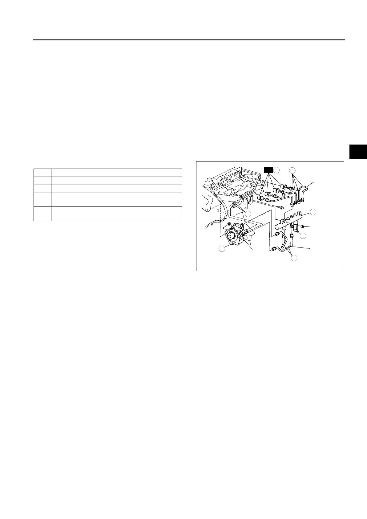
SUPPLY PUMP REMOVAL/INSTALLATION
A6E401213350201
Caution
• Fuel line spills and leakage on the parts are dangerous. Fuel can ignite and also deteriorate the
parts. To prevent this, always cover the mouths of the removed parts in the fuel system with rags
to soak up the fuel.
• To prevent the fuel injection pipe from clogging, be careful that foreign material has not entered
the pipe. Also, be sure to tighten the bolts with the specified tightening torque when installing the
fuel injection pipe.
• To prevent fuel leakage, follow the procedure indicated in the workshop manual when removing
and installing the fuel injector.
• The fuel injection pipe can be removed and reinstalled up to five times. Be sure to record in the
service record when removing and installing the fuel injection pipe. If removing it for the sixth
time, be sure to replace it with a new one.
1. Disconnect the negative battery cable.
2. Complete the “BEFORE REPAIR PROCEDURE”. (See F2–45 BEFORE REPAIR PROCEDURE.)
3. Remove in the order indicated in the table.
.
4. Install in the reverse order of removal.
5. Complete the “AFTER REPAIR PROCEDURE”.
(See F2–45 AFTER REPAIR PROCEDURE.)
Common Rail Installation Note
1. Temporarily tighten the common rail.
2. Temporarily tighten the injection pipes.
3. Fully tighten the injector side injection pipes, then tighten the common rail side.
Tightening torque
50—60 N·m {5—6 kgf·m, 37—44 ft·lbf}
4. Fully tighten the supply pump side and common rail side injection pipes.
Tightening torque
50—60 N·m {5—6 kgf·m, 37—44 ft·lbf}
5. Fully tighten the common rail.
Tightening torque
20—30 N·m {2.0—3.1 kgf·m, 15—22 ft·lbf}
End Of Sie
1 Injection pipe
2 Nozzle seal
3 Return fuel hose
4
Common rail
(See F2–53 Common Rail Installation Note)
5
Supply pump
(See B2–17 Supply Pump Pulley Removal Note)
19—25
{1.9—2.6, 14—18}
19—25
{1.9—2.6,
14—18}
50—60
{5—6,
37—44}
50—60
{5—6, 37—44}
N·m {kgf·m, ft·lbf}
A
R
A
5
4
3
1
2
1
A6E40122033