ELECTRONIC 4WD CONTROL SYSTEM
M–69
M
1. Apply sealant to the coupling case surface that contacts the rear differential case.
2. Install the coupling unit to the rear differential so
that the two tabs on the coupling unit engage the
rear differential grooves (two locations).
Tightening torque
22.6—26.4 N·m {2.4—2.6 kgf·m, 16.7—19.4
ft·lbf}
End Of Sie
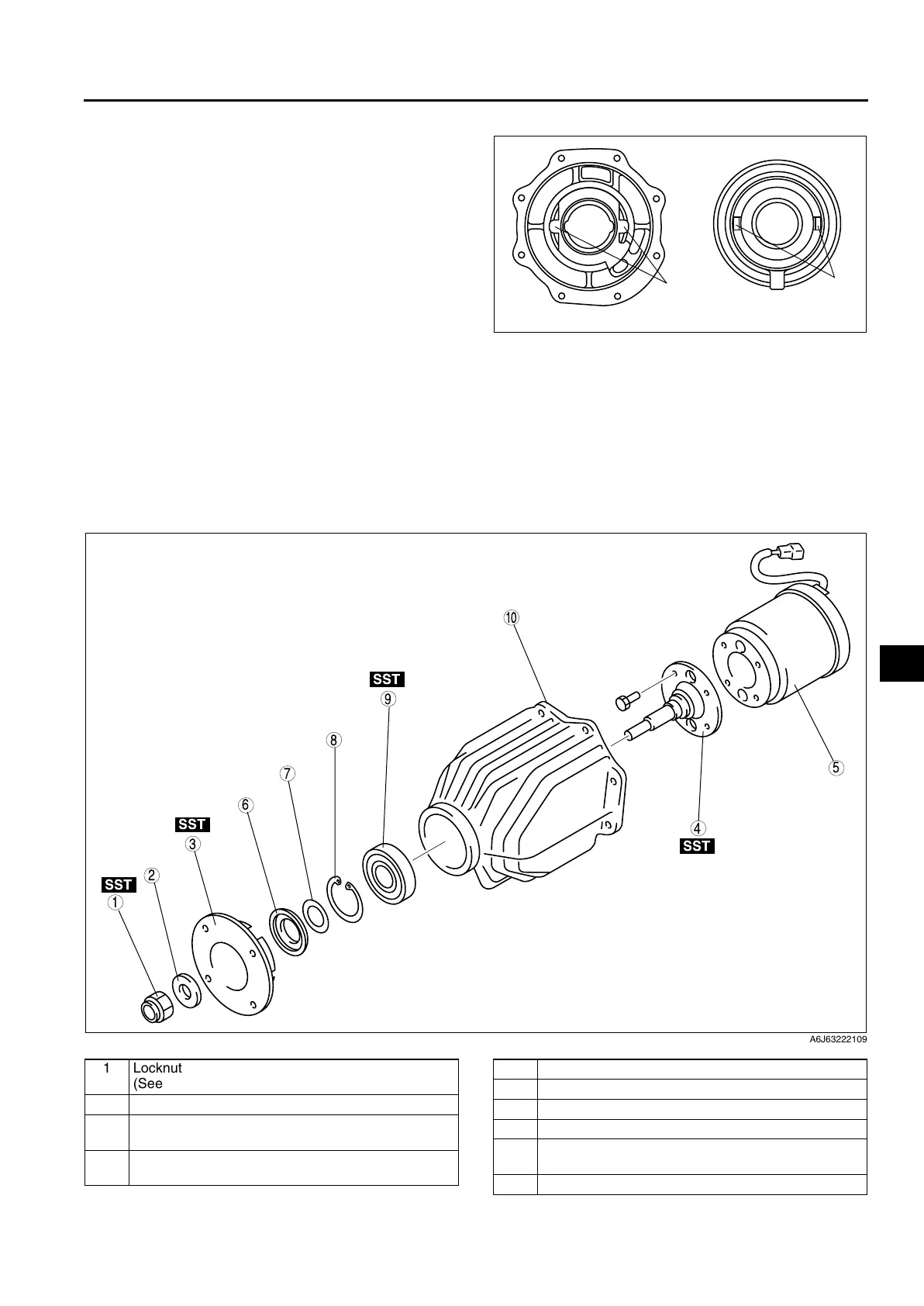
COUPLING COMPONENT DISASSEMBLY
A6E632227100215
Warning
• The engine stand is equipped with a self-lock mechanism, however, if the coupling unit is in a
tilted condition, the self-lock mechanism could become inoperative. If the coupling unit
unexpectedly rotates it could cause injury, therefore do not maintain the coupling unit in a tilted
condition. When turning the coupling unit, grasp the rotation handle firmly.
.
GROOVE
REAR DIFFERENTIAL COUPLING UNIT
TA B
A6E63222108
SST
SST
SST
SST
9
8
7
5
4
3
1
2
10
6
A6J63222109
1 Locknut
(See M–70 Locknut Disassembly Note)
2Washer
3 Companion flange
(See M–70 Companion Flange Disassembly Note)
4 Output shaft
(See M–71 Output Shaft Disassembly Note)
5 Coupling component
6Oil seal
7Shim
8 Retaining ring
9 Bearing
(See M–71 Bearing Disassembly Note)
10 Coupling case