ON-BOARD DIAGNOSTIC
F2–113
F2
DTC P0118
A6E407001082215
Diagnostic procedure
DTC P0118 ECT sensor circuit high input
DETECTION
CONDITION
• PCM monitors input voltage from ECT sensor while engine is running. If input voltage from ECT sensor is
above 5.0 V, PCM determines ECT sensor circuit high input.
POSSIBLE
CAUSE
• ECT sensor malfunction
• Connector or terminal malfunction
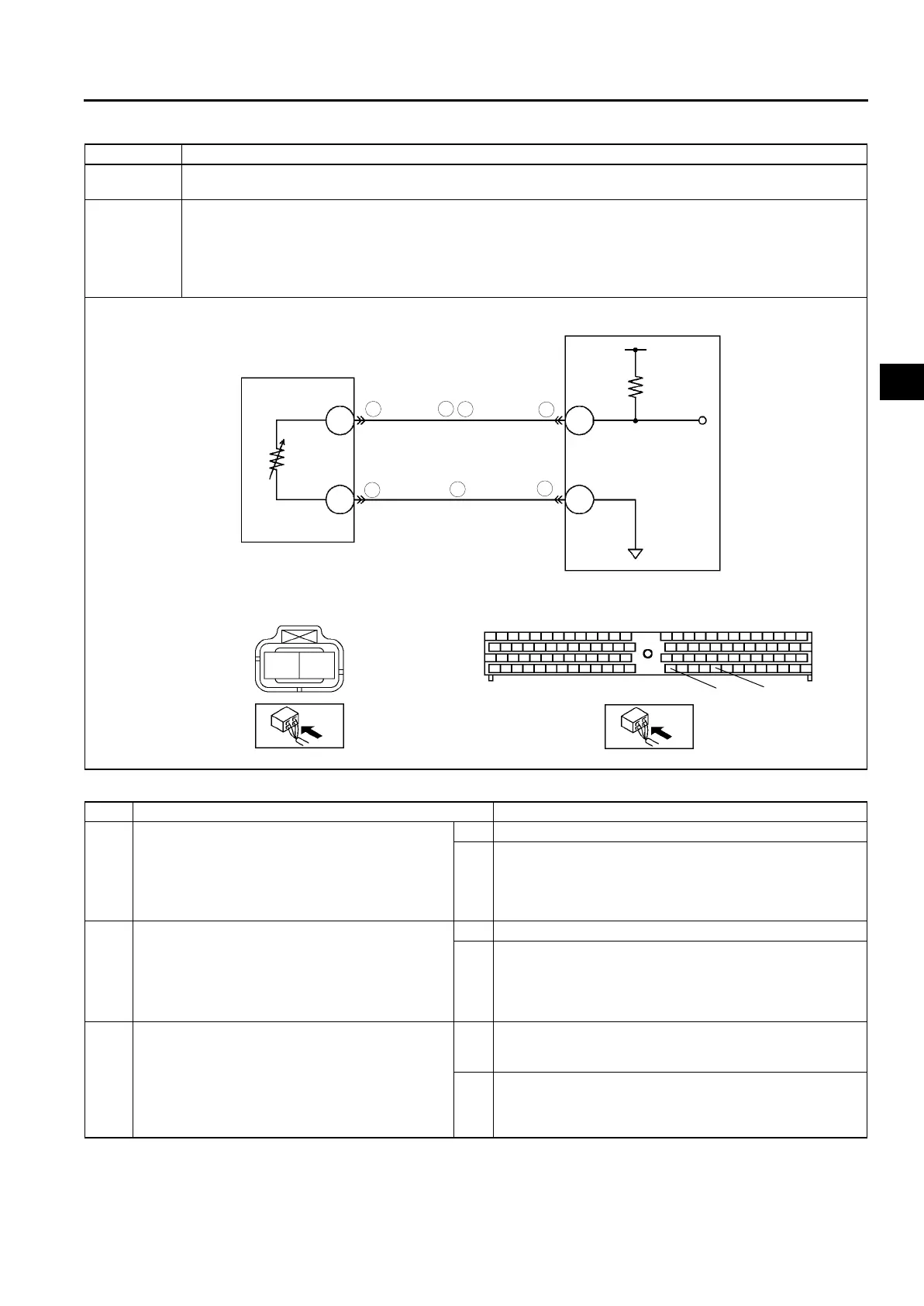
• Short to power circuit in wiring between ECT sensor terminal A and PCM terminal 87
• Open circuit in wiring between ECT sensor terminal A and PCM terminal 87
• Open circuit in wiring between ECT sensor terminal B and PCM terminal 91
• PCM malfunction
STEP INSPECTION ACTION
1 PERFORM DTC CONFIRMATION PROCEDURE
• Perform “DTC Confirmation Procedure”.
(See F2–85 DTC CONFIRMATION
PROCEDURE)
• Is same DTC present during KOEO or KOER
self-test?
Yes Go to next step.
No Intermittent concern exists. Go to “Intermittent Concern
Troubleshooting”.
(See F2–227 INTERMITTENT CONCERN
TROUBLESHOOTING)
2 INSPECT POOR CONNECTION OF ECT
SENSOR CONNECTOR
• Turn engine switch to OFF.
• Inspect for poor connection (damaged, pulled-
out terminals, corrosion, etc.).
• Is there any malfunction?
Yes Repair or replace suspected terminal, go to Step 7.
No Go to next step.
3 CLASSIFY ECT SENSOR MALFUNCTION OR
HARNESS MALFUNCTION
• Turn engine switch to ON (Engine OFF).
• Connect jumper wire between ECT sensor
connector terminals.
• Access ECT PID using WDS or equivalent.
• Is ECT PID below 1.0 V?
Yes Replace ECT sensor, go to Step 7.
(See F2–76 ENGINE COOLANT TEMPERATURE (ECT)
SENSOR REMOVAL/INSTALLATION)
No Go to next step.
5
6
2
5
4
6
2
ECT SENSOR
A
B
PCM
87
91
B
A
91
87
ECT SENSOR
HARNESS SIDE CONNECTOR
PCM
HARNESS SIDE CONNECTOR