FUEL SYSTEM
F2–51
F2
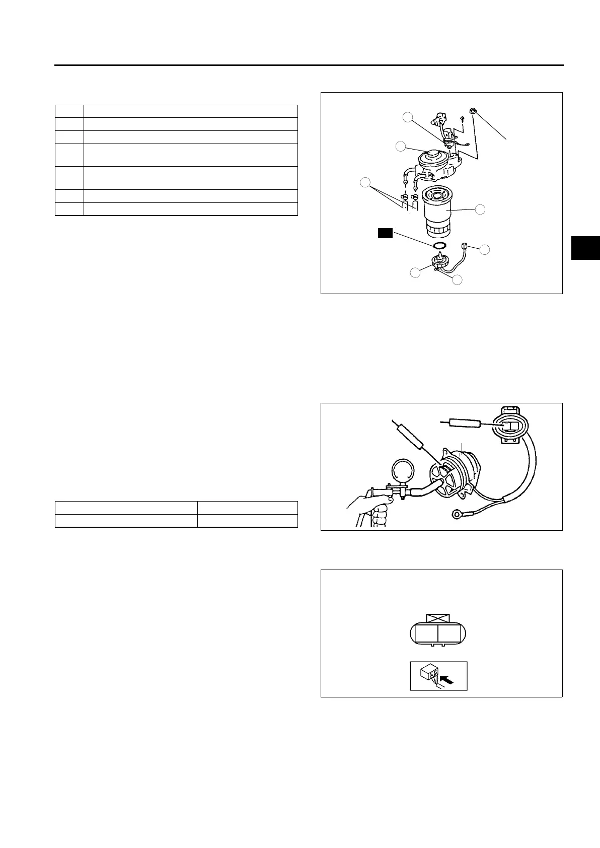
FUEL FILTER COMPONENT DISASSEMBLY/ASSEMBLY
A6E401234802202
1. Disassemble in the order indicated in the table.
.
2. Assemble in the reverse order of removal.
Sedimentor Switch Installation Note
1. Apply a small amount of fuel to a new O-ring.
2. Tighten the sedimentor switch enough to the fuel
filter by hand.
Fuel Filter Installation Note
1. Apply a small amount of fuel to the fuel filter O-ring.
2. Tighten the fuel filter approx. 3/4 by hand after the O-ring contacts the priming pump.
End Of Sie
FUEL WARMER INSPECTION
A6E401234802203
For Cold Areas
1. Remove the fuel warmer. (See F2–51 FUEL FILTER COMPONENT DISASSEMBLY/ASSEMBLY.)
2. Verify that the resistance between terminal A and
the fuel warmer body is within the specification
when vacuum of –31.3— –38.0 kPa {–235— –
285 mmHg, –9.2— –11.2 inHg} is applied to port
A of the fuel warmer.
• If as specified, carry out the “Circuit Open/
Short Inspection”.
• If not as specified, replace the fuel warmer.
Specification
Circuit Open/Short Inspection
1. Inspect for open/short circuit in the following
wiring harnesses.
• If there is open/short circuit, repair or replace
wiring harnesses.
Open circuit
• If there is no continuity, the circuit is open. Repair
or replace the harness.
— Fuel warmer terminal A (harness-side) and
GND
— Fuel warmer terminal B (harness-side) and
power supply
Short circuit
• If there is continuity, the circuit is shorted. Repair or replace the harness.
— Fuel warmer terminal B (harness-side) and GND
End Of Sie
1 Connector
2 Fuel hose
3 Priming pump
4
Fuel filter
(See F2–51 Fuel Filter Installation Note)
5
Sedimentor switch
(See F2–51 Sedimentor Switch Installation Note)
6 Drain plug
7 Fuel warmer
R
17.6—26.5
{1.8—2.7,
13.0—19.8}
7
5
4
3
6
1
2
N.m {kgf·m, ft·lbf}
A6E40122036
Ambient temperature (°C {°F}) Resistance (ohms)
20 {68} 0.5—1.5
FUEL WARMER
B
A6E40122013
AB
FUEL WARMER
HARNESS SIDE CONNECTOR
A6E40122014












 To Next Page