WARNING AND INDICATOR SYSTEM
T–27
T
FUEL GAUGE SENDER UNIT REMOVAL/INSTALLATION
A6E811860960201
Fuel Gauge Sender Unit
2WD
• There are no changes from the current fuel gauge sender unit removal/installation procedure.
4WD
1. Remove the fuel gauge sender unit. (See F1–26 FUEL PUMP UNIT REMOVAL/INSTALLATION.)
2. Install in the reverse order of removal.
Fuel Gauge Sender Sub-Unit
Warning
• Fuel line spills and leakage are dangerous. Fuel can ignite and cause serious injuries or death and
damage. Fuel can also irritate skin and eyes. To prevent this, do not damage the sealing surface of
the fuel gauge sender sub-unit when removing or installing.
Caution
• Disconnecting/connecting the quick release connector without cleaning it may possibly cause
damage to the fuel pipe and quick release connector. Always clean the quick release connector
joint area before disconnecting/connecting using a cloth or soft brush, and make sure that it is
free of foreign material.
1. Complete the “BEFORE REPAIR PROCEDURE”.
2. Disconnect the negative battery cable.
3. Complete the following in order to the work area.
(1) Loosen the bolt of the fuel tank strap.
(2) Lower the fuel tank to a position where the SST can be attached from the service hole cover.
4. Remove the rear seat cushion.
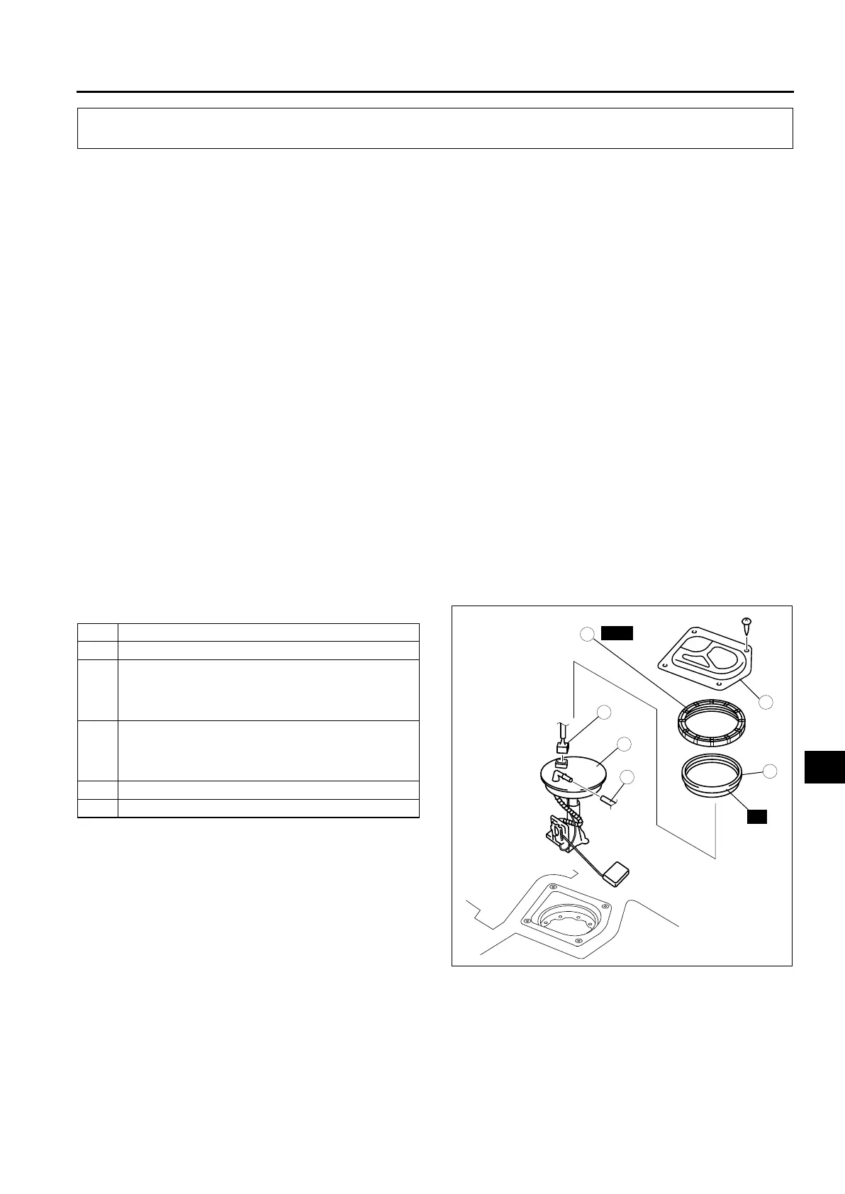
5. Remove in the order indicated in the table.
6. Install in the reverse order of removal.
7. Complete the “AFTER REPAIR PROCEDURE”.
8. Complete the “Fuel leak inspection after fuel
gauge sender sub-unit installation.“ (See T–28
Fuel leak inspection after fuel gauge sender sub-
unit installation.)
WARNING AND INDICATOR SYSTEM
1 Service hole cover
2 Connector
3 Plastic fuel hose (fuel tank side, transfer hose part)
(See F1–29 FUEL HOSE (FUEL TANK SIDE,
TRANSFER HOSE PART) REMOVAL/
INSTALLATION)
4 Fuel gauge sender cap
(See T–28 Fuel gauge sender cap removal note)
(See T–28 Fuel Gauge Sender Cap Installation
Note)
5 Packing
6 Fuel gauge sender sub-unit
3
1
4
5
6
2
80—90 {8.2—9.1, 60—66}
N·m {kgf·m, ft·lbf}
R
SST
A6E81182001












 To Next Page