OUTLINE
F1–3
F1
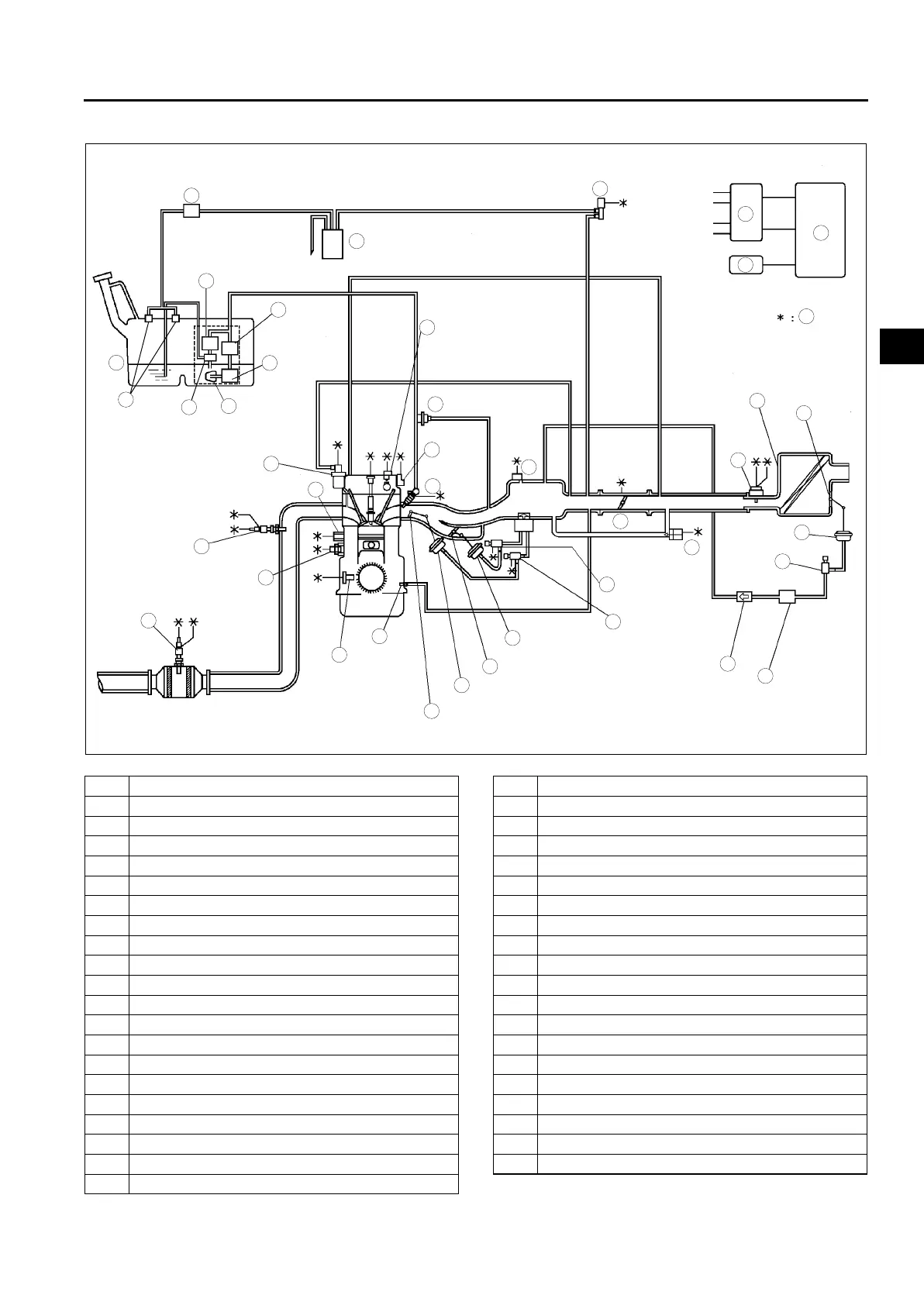
CONTROL SYSTEM DIAGRAM (4WD)
A6E390218881204
.
* : Equipped for L3 engine model
End Of Sie
9
8
7
5
4
3
10
19
18
17
15
16
14
13
11
12
20
29
28
27
25
26
24
23
21
22
30
39
38
37
35
33
36
31
32
40
6
1
2
34
41
A6E39022000
1PCM
2 Ignition coil
3 Generator
4* VAD shutter valve
5 Air cleaner
6 MAF sensor
7* VAD shutter valve actuator
8* VAD control solenoid valve
9* Vacuum chamber
10* VAD check valve (one-way)
11 IAC valve
12 Purge solenoid valve
13 TP sensor
14 MAP sensor
15* VIS control solenoid valve
16 Variable tumble control solenoid valve
17* VIS shutter valve actuator
18* VIS shutter valve
19 VTCS shutter valve actuator
20 VTCS shutter valve
21 Fuel injector
22* OCV
23 CMP sensor
24 EGR valve
25 Knock sensor
26 ECT sensor
27 PCV valve
28 CKP sensor
29 HO2S (front)
30 HO2S (rear)
31 Charcoal canister
32 Check valve (two-way)
33 Pressure regulator
34 Fuel filter (high-pressure)
35 Fuel pump
36 Fuel filter (low-pressure)
37 Fuel tank
38 Rollover valve
39 Pulsation damper
40 Fuel pump (transfer)
41 To PCM