ON-BOARD DIAGNOSTIC
F2–143
F2
DTC P0380
A6E407001082233
Diagnostic procedure
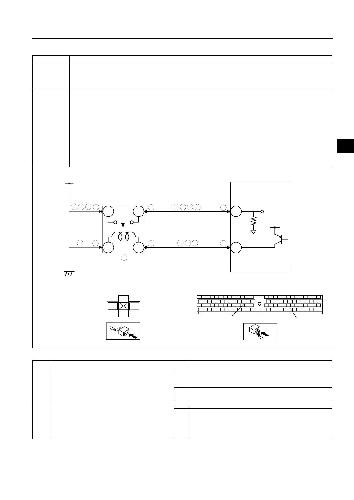
DTC P0380 Glow plug relay circuit malfunction
DETECTION
CONDITION
• PCM monitors input voltage from glow plug relay while engine is running. PCM determines glow plug relay
circuit malfunction if input voltage from glow plug relay is as following:
— 1.0 V or below when glow plug relay is on.
— 4.0 V or above when glow plug relay is off.
POSSIBLE
CAUSE
• Glow plug relay malfunction
• Connector or terminal malfunction
• Short to GND in wiring between glow plug relay terminal D and PCM terminal 68
• Short to GND in wiring between glow plug fuse and glow plug relay terminal A
• Short to GND in wiring between glow plug relay terminal C and PCM terminal 86
• Short to power circuit in wiring between glow plug relay terminal D and PCM terminal 68
• Short to power circuit in wiring between glow plug relay terminal C and PCM terminal 86
• Glow plug relay power and signal circuits short each other
• Open circuit in wiring between glow plug fuse and glow plug relay terminal A
• Open circuit in wiring between glow plug relay terminal B and GND
• Open circuit in wiring between glow plug relay terminal D and PCM terminal 68
• Open circuit in wiring between glow plug relay terminal C and PCM terminal 86
• PCM malfunction
STEP INSPECTION ACTION
1 VERIFY RELATED REPAIR INFORMATION
AVAILABILITY
• Check for related Service Information
availability.
• Is any related repair information available?
Yes Perform repair or diagnosis according to available Service
Information.
• If vehicle is not repaired, go to next step.
No Go to next step.
2 INSPECT POOR CONNECTION OF GLOW
PLUG RELAY CONNECTOR
• Turn engine switch to OFF.
• Inspect for poor connection (damaged, pulled-
out terminals, corrosion, etc.).
• Is there any malfunction?
Yes Repair or replace suspected terminal, go to Step 9.
No Go to next step.
A
B
C
D
GLOW FUSE
GLOW PLUG RELAY
A
D
B
C
68
86
68
86
PCM
5
4
3
6
2
2
6
2
2
3
5
9
8
4
3
9
8
PCM
HARNESS SIDE CONNECTOR
7
GLOW PLUG RELAY
HARNESS SIDE CONNECTOR












 To Next Page