COOLING SYSTEM
E–5
E
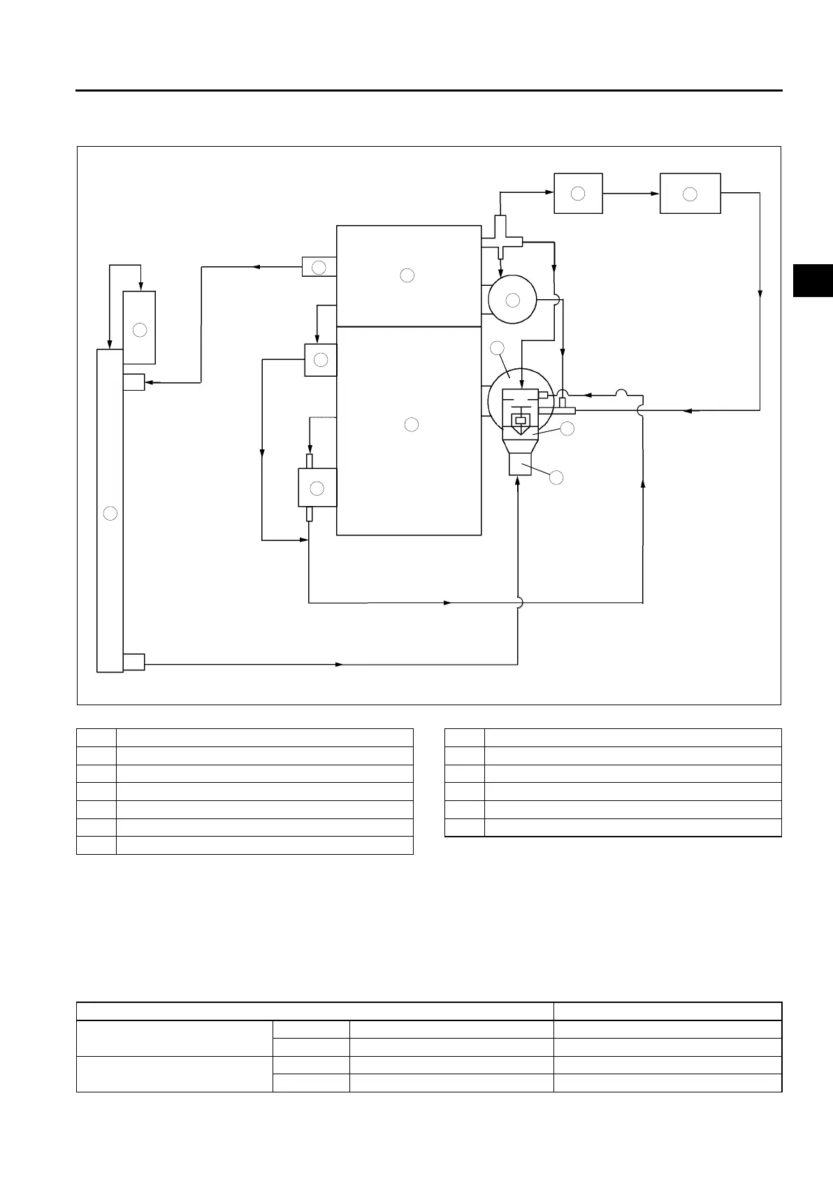
COOLING FLOW DIAGRAM
A6E363002000202
MZR-CD (RF Turbo)
.
End Of Sie
COOLING FAN
A6E363002000204
MZR-CD (RF Turbo)
Structure
• Electric cooling fans No.1 and No.2, operated according to a cooling fan control signal from the PCM, have
been adopted. Due to this, engine noise is reduced and rapid warm-up is possible.
• Cooling fans No.1 and No.2 are attached to the radiator cowling.
• The cooling fan motor output has been changed.
Cooling fan, Fan motor specification
End Of Sie
9
8
7
5
4
3
1
2
10
13
11
12
6
A6E3600W300
1Radiator
2 Coolant reservoir tank
3 Water outlet
4EGR water cooler
5 Engine oil cooler
6 Cylinder head
7 Cylinder block
8 Turbocharger
9 Water pump
10 Thermostat case
11 Thermostat cover
12 Water heater system
13 Heater core
ITEM Specification
Cooling fan No.1
Fan Number of blades (sheet) 7
Motor Motor output (W) 70
Cooling fan No.2
Fan Number of blades (sheet) 5
Motor Motor output (W) 80