F2–52
FUEL SYSTEM
SEDIMENTOR WATER DRAINING
A6E401234802204
1. Disconnect the negative battery cable.
2. Complete the “BEFORE REPAIR PROCEDURE”. (See F2–45 BEFORE REPAIR PROCEDURE.)
3. Loosen the drain plug located at the bottom of the fuel filter.
4. Pump the priming pump and drain the water.
5. After all the water has been drained, tighten the drain plug.
6. Complete the “AFTER REPAIR PROCEDURE”. (See F2–45 AFTER REPAIR PROCEDURE.)
7. Reconnect the negative battery cable.
End Of Sie
SEDIMENTOR SWITCH INSPECTION
A6E401213840201
Note
• Perform the following test only when directed.
1. Disconnect the negative battery cable.
2. Complete the “BEFORE REPAIR PROCEDURE”. (See F2–45 BEFORE REPAIR PROCEDURE.)
3. Drain fuel from the fuel filter. (See F2–52 SEDIMENTOR WATER DRAINING.)
4. Remove the sedimentor switch.
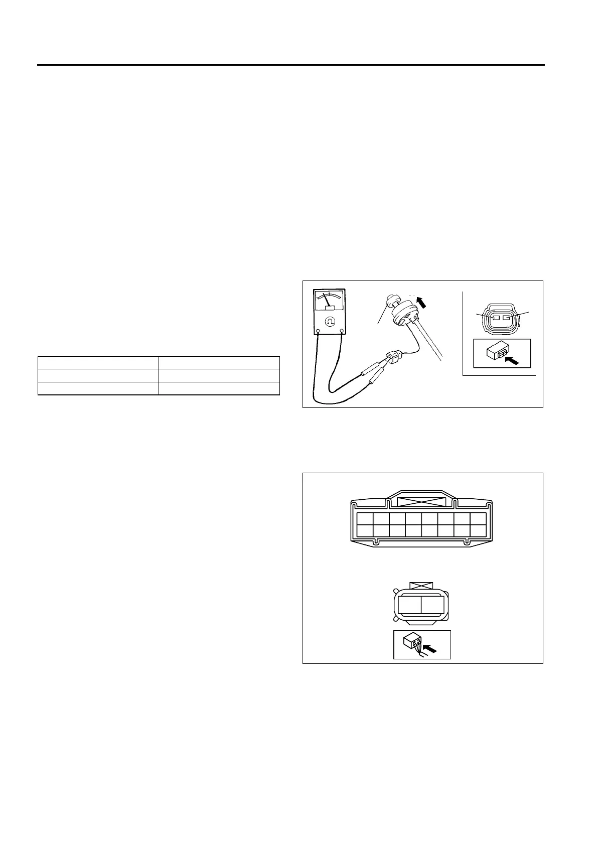
5. Inspect for continuity of the sedimentor switch
using an ohmmeter.
• If as specified, inspect the following and carry
out the “Circuit Open/Short Inspection.”
• If not as specified, replace the sedimentor
switch.
Specification
6. Install the sedimentor switch.
7. Reconnect the negative battery cable.
8. Complete the “AFTER REPAIR PROCEDURE”.
(See F2–45 AFTER REPAIR PROCEDURE.)
Circuit Open/Short Inspection
1. Inspect the following wiring harnesses for open or
short (continuity check).
Open circuit
• If there is no continuity, the circuit is open.
Repair or replace the harness.
— Sedimentor switch terminal B (harness-
side) and GND.
— Sedimentor switch terminal A (harness-
side) and instrument cluster terminal 1C.
Short circuit
• If there is continuity, the circuit is shorted.
Repair of replace the harness.
— Sedimentor switch terminal A (harness-
side) and GND.
— Sedimentor switch terminal B (harness-
side) and power supply.
End Of Sie
Float Continuity
Up Yes
Down No
UP
DOWN
FLOAT
A
B
A6E40122015
1O 1M 1K 1I 1G 1E 1C 1A
1P 1N 1L 1J 1H 1F 1D 1B
INSTRUMENT CLUSTER CONNECTOR
SEDIMENTOR SWITCH
HARNESS SIDE CONNECTOR
A
B
A6E40122016












 To Next Page