INTAKE-AIR SYSTEM
F2–41
F2
Open circuit
• If there is no continuity, the circuit is open. Repair or replace the harness.
— VBC solenoid valve terminal A (harness-side) and PCM control relay terminal C
— VBC solenoid valve terminal B (harness-side) and PCM connector terminal 67
Short circuit
• If there is continuity, the circuit is shorted. Repair or replace the harness.
— VBC solenoid valve terminal A (harness-side) and GND
— VBC solenoid valve terminal B (harness-side) and power supply
End Of Sie
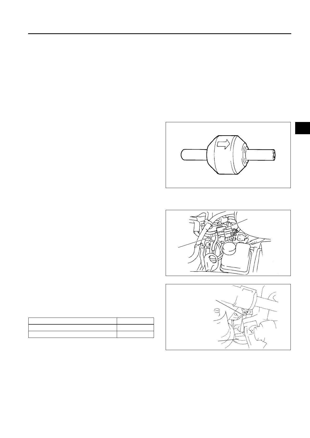
VARIABLE BOOST CONTROL (VBC) CHECK VALVE INSPECTION
A6E401013710202
1. Remove the VBC check valve. (See F2–35 VACUUM TUBE ROUTING DIAGRAM.)
2. Blow through port A and verify that the air flows from port B.
• If not as specified, replace the VBC check valve.
3. Blow through port B and verify that the air does
not flow from port A.
• If not as specified, replace the VBC check
valve.
End Of Sie
VARIABLE SWIRL CONTROL (VSC) VALVE ACTUATOR INSPECTION
A6E401013110201
1. Disconnect the vacuum hose from the VSC
solenoid valve.
2. Connect a vacuum pump to the vacuum hose.
3. Apply vacuum and verify that the rod moves as
specified.
• If not as specified, replace the intake
manifold.
Specification
End Of Sie
A
B
A6E40102015
Vacuum (kPa {mmHg, inHg}) Rod movement
Below –20 {–150, –5.9} Starts to move
Above –69.4 {–521, –20.5} Fully pulled
VSC
SOLENOID VALVE
VACUUM
HOSE
A6E40102016
ROD
VSC SHUTTER
VALVE ACTUATOR
A6E40102017











 To Next Page