F2–80
CONTROL SYSTEM
CAMSHAFT POSITION (CMP) SENSOR REMOVAL/INSTALLATION
A6E404018200201
Caution
• When foreign material, such as iron chips, gets on the CMP sensor, it can cause abnormal output
from the sensor because of flux turbulence and adversely affect engine control. Be sure there is
no foreign material on the CMP sensor when replacing.
• Do not forcefully pull the wiring harness of the CMP sensor. Doing so will break the harness.
1. Disconnect the negative battery cable.
2. Remove the engine cover.
3. Remove in the order indicated in the table.
4. Install in the reverse order of removal.
O-ring Installation Note
1. Apply engine oil to new O-ring thinly and install it
as does not damage.
End Of Sie
CAMSHAFT POSITION (CMP) SENSOR INSPECTION
A6E404018200202
Note
• Perform the following test only when directed.
Caution
• When foreign material, such as iron chips, gets on the CMP sensor, it can cause abnormal output
from the sensor because of flux turbulence and adversely affect engine control. Be sure there is
no foreign material on the CMP sensor when replacing.
• Do not forcefully pull the wiring harness of the CMP sensor. Doing so will break the harness.
Visual Inspection
1. Verify that the CMP sensor and the pulsar are free of any metallic shavings or particles.
• If any are found on the CMP sensor and the pulsar, clean them off.
Air Gap Inspection
1. Disconnect the negative battery cable.
2. Remove the gear cover.
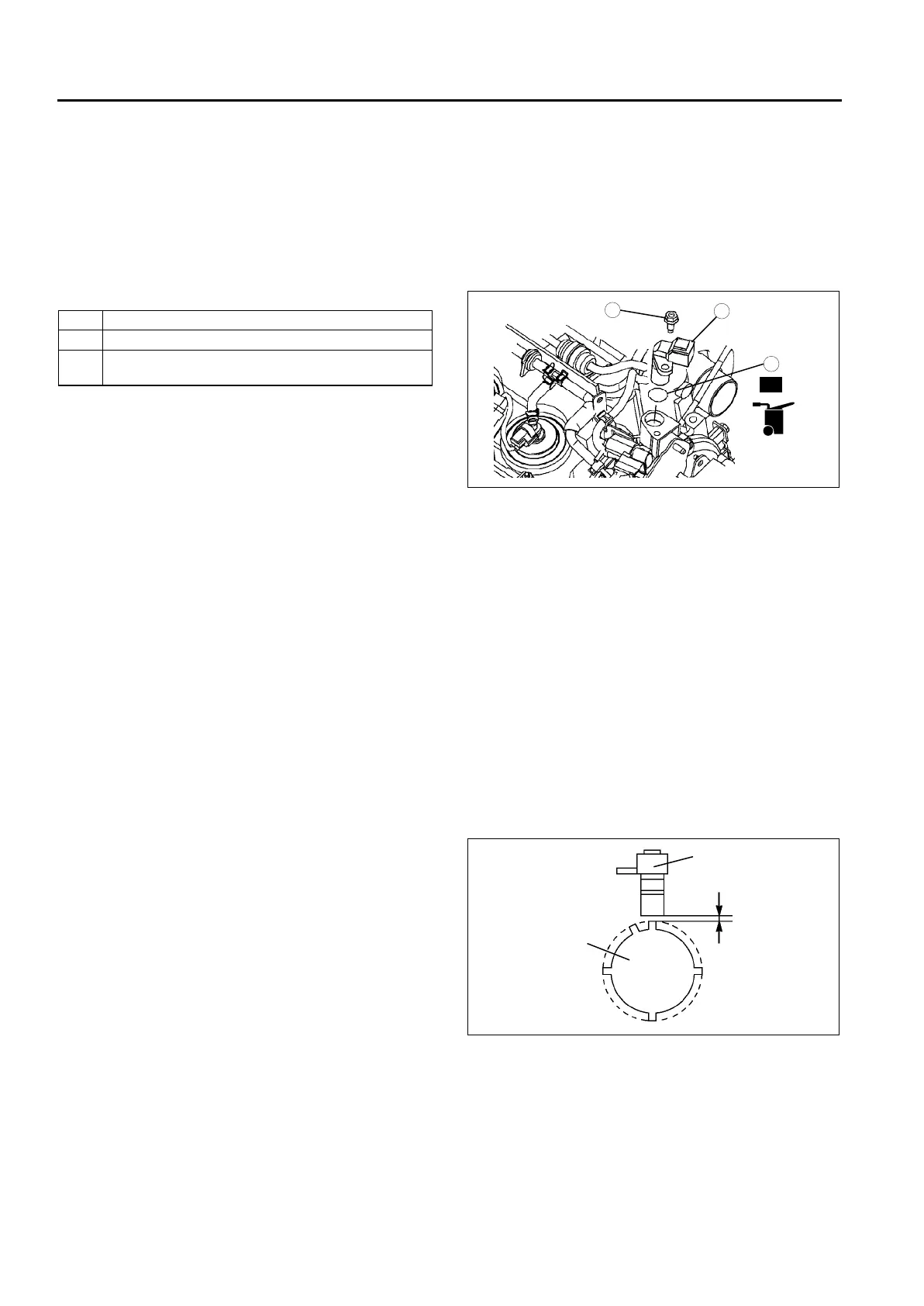
3. Verify that clearance A between the CMP sensor
and the pulsar is within the specification.
• If not as specified, replace the CMP sensor.
Clearance A
0.5—1.5 mm {0.020—0.059 in}
1 CMP sensor installation bolt
2 CMP sensor
3 O-ring
(See F2–80 O-ring Installation Note)
N·m {kgf·cm, in·lbf}
3
1
2
7.8—10.8
{80—110, 69.1—95.5}
R
OIL
A6E40702050
CMP SENSOR
CLEARANCE A
PULSAR
A6E40702051