ON-BOARD DIAGNOSTIC
K2–139
K2
End Of Sie
DTC P0720
A6E577018901211
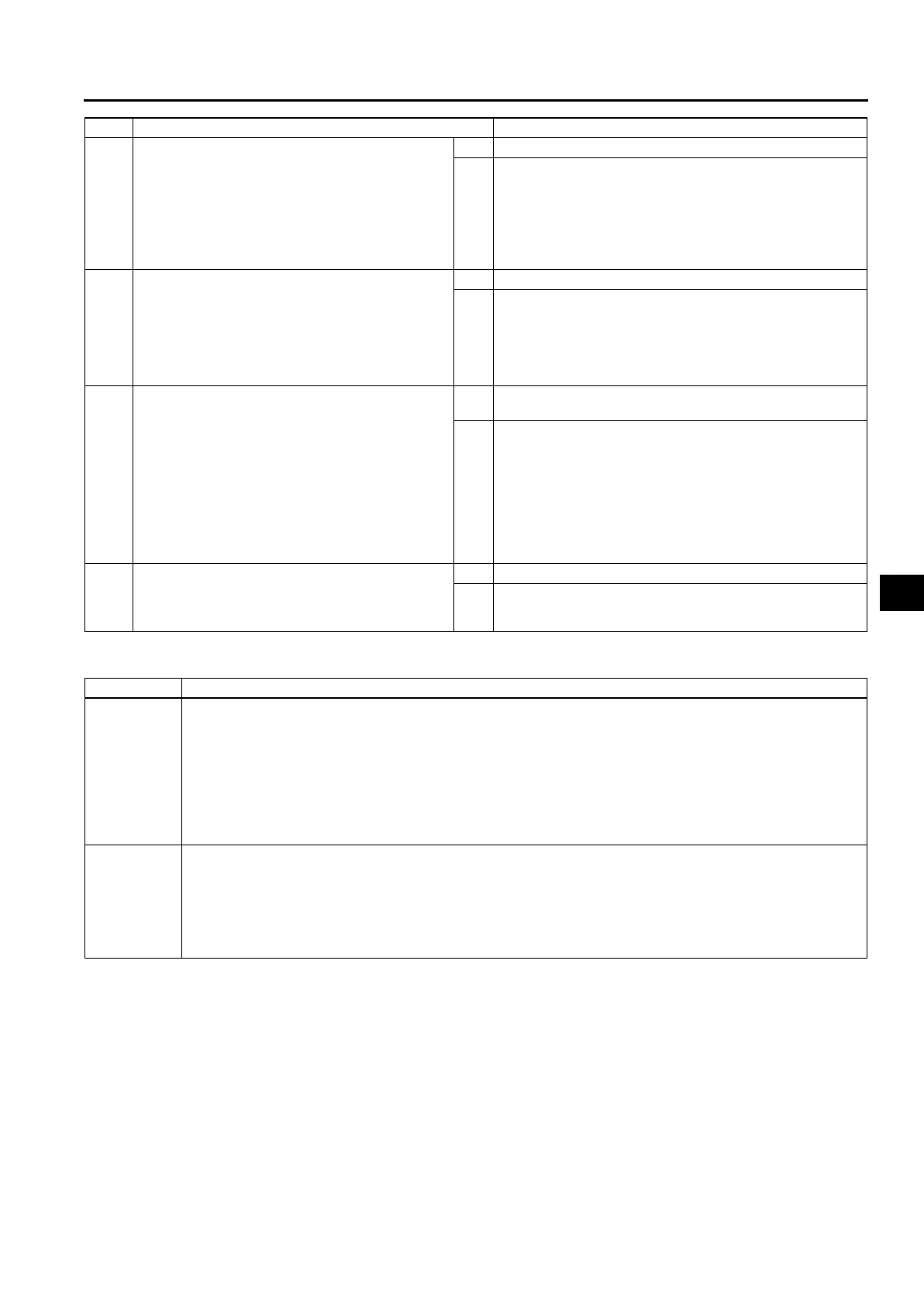
10 INSPECT INPUT/TURBINE SPEED SENSOR
CONNECTOR FOR POOR CONNECTION
• Disassemble the transaxle.
• Disconnect input/turbine speed sensor
connector.
• Check for poor connection (damaged, pulled-
out terminals, corrosion, etc.).
• Are terminals okay?
Yes Go to next step.
No Repair terminals, then go to Step 12.
11 INSPECT INPUT/TURBINE SPEED SENSOR
RESISTANCE
• Measure resistance between input/turbine
speed sensor.
• Is resistance within 513—627 ohms between
input/turbine speed sensor connector terminal
A and B (part side)?
Yes Repair or replace coupler component, then go to next step.
No Replace input/turbine speed sensor, then go to next step.
12 VERIFY TROUBLESHOOTING OF DTC P0715
COMPLETED
• Make sure to reconnect all disconnected
connectors.
• Clear DTC from memory using WDS or
equivalent.
• Drive vehicle with vehicle speed 40 km/h {25
mph} or above and engine speed 1,500 rpm
or above for 2 second or more
• Repeat Step ii two times.
• Is same DTC present?
Yes Replace TCM, then go to next step.
(See K2–96 TCM REMOVAL/INSTALLATION.)
No Go to next step.
13 VERIFY AFTER REPAIR PROCEDURE
• Perform “After Repair Procedure”.
(See K2–124 AFTER REPAIR PROCEDURE.)
• Is there any DTC present?
Yes Go to applicable DTC inspection.
No Troubleshooting completed.
STEP INSPECTION ACTION
DTC P0720 Vehicle speedometer sensor (VSS) malfunction (open/short)
DETECTION
CONDITION
• Parking gear rotation detected by VSS is 150 rpm (Vehicle speed: 5—6 km/h) or less while intermediate
sensor signal is 1,400 rpm or greater in D range for 2 second or more.
Diagnostic support note:
• This is a continuous monitor (CCM).
• MIL illuminates if TCM detects the above malfunction conditions in two consecutive drive cycles.
• PENDING CODE is available.
• FREEZE FRAME DATA is available.
• AT warning light indication.
• DTC is stored in TCM memory.
POSSIBLE
CAUSE
• Open circuit between vehicle speedometer sensor terminal B and TCM terminal 1M
• Open circuit between vehicle speedometer sensor terminal A and TCM terminal 1V
• Short to ground between vehicle speedometer sensor terminal B and TCM terminal 1M
• Short to ground between vehicle speedometer sensor terminal A and TCM terminal 1V
• Vehicle speedometer sensor malfunction
• Damaged connectors between vehicle speedometer sensor to TCM
• TCM malfunction











 To Next Page