CONTROL SYSTEM
F2–81
F2
Resistance Inspection
1. Disconnect the negative battery cable.
2. Remove the engine cover.
3. Disconnect the CMP sensor connector.
4. Inspect the resistance between the terminals
under the following condition.
• If not as specified, replace the CMP sensor.
Specification
Circuit Open/Short Inspection
1. Inspect for open/short circuit in the following
wiring harnesses.
• if there is open/short circuit, repair or replace
wiring harnesses.
Open circuit
• CMP sensor terminal A and PCM terminal 81
• CMP sensor terminal B and PCM terminal 55
Short circuit
• CMP sensor terminal A and PCM terminal 81 to GND
• CMP sensor terminal B and PCM terminal 55 to GND
End Of Sie
CRANKSHAFT POSITION (CKP) SENSOR REMOVAL/INSTALLATION
A6E404018230201
Caution
• When foreign material, such as iron chips, gets on the CKP sensor, it can cause abnormal output
from the sensor because of flux turbulence and adversely affect engine control. Be sure there is
no foreign material on the CKP sensor when replacing.
• Do not forcefully pull the wiring harness of the CKP sensor. Doing so will break the harness.
1. Disconnect the negative battery cable.
2. Remove the crankshaft pulley. (See B2–9 TIMING BELT REMOVAL/INSTALLATION.)
3. Remove the lower timing belt cover. (See B2–9 TIMING BELT REMOVAL/INSTALLATION.)
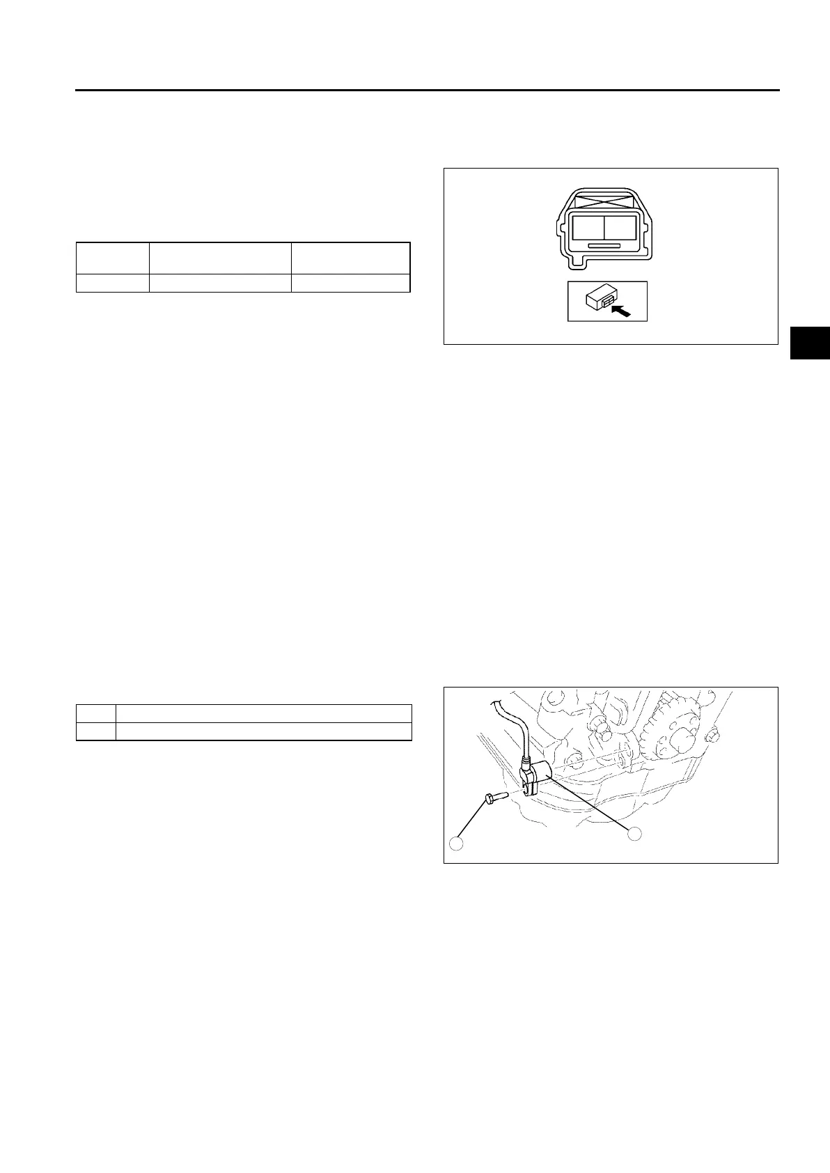
4. Remove in the order indicated in the table.
5. Install in the reverse order of removal.
End Of Sie
Terminal
Atmospheric
temperature (°C {°F})
Resistance
(kilohm)
A—B 20 {68} 1.85—2.45
A
B
A6E40702052
1 CKP sensor installation bolt
2 CKP sensor
N·m {kgf·cm, in·lbf}
16—23 {1.6—2.4, 12—17}
1
2
A6E40702053