AUTOMATIC TRANSAXLE
K2–85
K2
TRANSAXLE FLUID TEMPERATURE (TFT) SENSOR REMOVAL/INSTALLATION
A6E571419010203
1. Remove the automatic transaxle. (See K2–99 AUTOMATIC TRANSAXLE AND TRANSFER REMOVAL/
INSTALLATION.)
2. Disassemble the automatic transaxle, and then remove the TFT sensor. (See Automatic Transaxle Workshop
Manual JA5A-EL)
3. Install a TFT sensor, and then assemble the automatic transaxle. (See Automatic Transaxle Workshop Manual
JA5A-EL)
4. Remove the automatic transaxle. (See K2–99 AUTOMATIC TRANSAXLE AND TRANSFER REMOVAL/
INSTALLATION.)
5. Carry out the line pressure test. (See K2–72 Line Pressure Test.)
6. Inspect the operation of the TR switch. (See K2–80 TRANSAXLE RANGE (TR) SWITCH INSPECTION.)
7. Inspect the operation of the selector lever. (See K2–117 SELECTOR LEVER INSPECTION.)
8. Carry out the mechanical system test. (See K2–72 MECHANICAL SYSTEM TEST.)
9. Carry out the road test. (See K2–75 ROAD TEST.)
End Of Sie
INPUT/TURBINE SPEED SENSOR INSPECTION
A6E571421550202
On-Vehicle Inspection
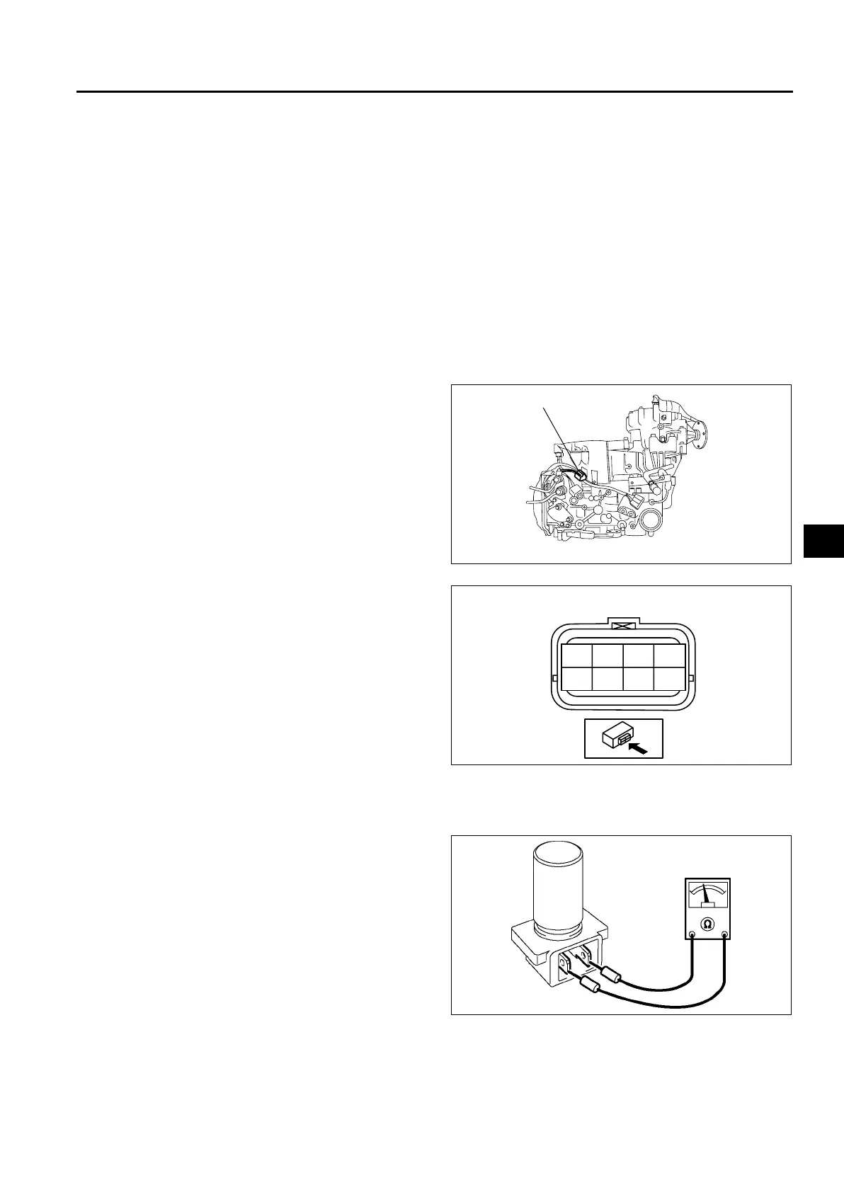
1. Disconnect the terminal component No.2
connector.
2. Measure resistance between the terminals E and
F.
• If not as specified, inspect the input/turbine
speed sensor. (See K2–85 Inspection of
Individual Part.)
Resistance (ATF temperature: 20 °C {68 °F})
513—627 ohms
3. Connect the terminal component No.2 connector.
Inspection of Individual Part
1. Remove the input/turbine speed sensor. (See K2–86 INPUT/TURBINE SPEED SENSOR REMOVAL/
INSTALLATION.)
2. Measure resistance between the terminals of the
input/turbine speed sensor.
• If not as specified, replace the input/turbine
speed sensor.
• If it is normal, replace the harness.
Resistance (ATF temperature: 20 °C {68 °F})
513—627 ohms
3. Install the input/turbine sensor. (See K2–86
INPUT/TURBINE SPEED SENSOR REMOVAL/
INSTALLATION.)
End Of Sie
TERMINAL COMPONENT No.2
A6E5714W117
ACEG
BDFH
A6E5714W118
AMU0517W051











 To Next Page