EMISSION SYSTEM
F2–59
F2
EGR VALVE REMOVAL/INSTALLATION
A6E401620300201
1. Disconnect the negative battery cable.
2. Remove the air cleaner. (See F2–36 INTAKE-AIR SYSTEM REMOVAL/INSTALLATION.)
3. Remove the common rail. (See F2–53 SUPPLY PUMP REMOVAL/INSTALLATION.)
4. Remove in the order indicated in the table.
.
5. Install in the reverse order of removal.
End Of Sie
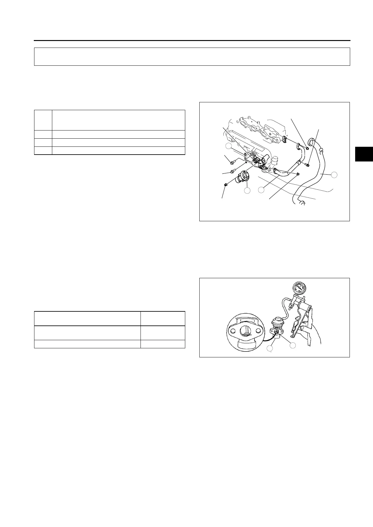
EGR VALVE INSPECTION
A6E401620300202
Note
• Perform the following test only when directed.
1. Remove the EGR valve. (See F2–36 INTAKE-AIR SYSTEM REMOVAL/INSTALLATION.)
2. Inspect for airflow between 1 and 2 when vacuum
is applied using a vacuum pump as shown in the
figure.
• If not as specified, replace the EGR valve.
Specification
End Of Sie
EMISSION SYSTEM
1
Air pipe
(See F2–36 INTAKE-AIR SYSTEM REMOVAL/
INSTALLATION)
2 EGR pipe
3EGR water cooler
4EGR valve
N·m {kgf·m, ft·lbf}
20—30
{2.0—3.1,
15—22}
22—26
{2.2—2.7,
16—19}
7.9—10.7 N·m
{80—109 kgf·cm,
70—94 in·lbf}
22—26
{2.2—2.7,
16—19}
38—51
{3.8—5.3,
28—37}
19—25
{1.9—2.6,
14—18}
39—44
{4.0—4.4,
29—32}
4
3
1
2
A6E40122023
Vacuum
kPa {mmHg, inHg}
Airflow
Below –25.0— –41.6
{–188— –312, –7.39 — –12.3}
Yes
Except above No
1
2
A6E40122024