CONTROL SYSTEM
F2–71
F2
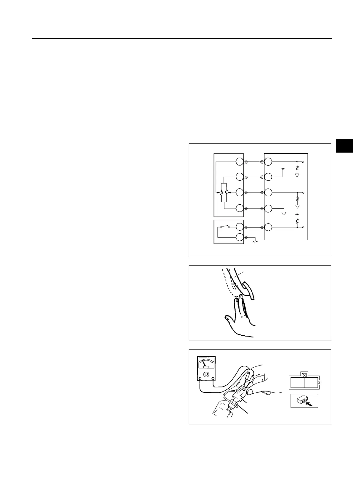
IDLE SWITCH ADJUSTMENT
A6E404041600202
Caution
• Adjusting the idle switch unnecessarily may adversely affect engine control. Therefore, adjust the
idle switch only when it is replaced.
1. Verify that the accelerator position sensor is normal.
2. Visually inspect all accelerator pedal components for looseness.
3. Loosen the locknut that secures the idle switch.
4. Verify that the power circuit voltage.
(1) Verify that the voltage between the PCM terminals 90 (power circuit) and 91(GND circuit) is 4.75—5.25 V.
Note
• Voltage at the PCM terminal 10 may deviate when the power circuit voltage is abnormal.
5. Depress the accelerator pedal by hand and
secure it when the voltage between the PCM
terminals 10 (accelerator position detection
signal) and 91 is within the range specified below.
Voltage range
0.9—1.1V (Target value: 1.0 V)
6. Turn the idle switch under the condition in Step 5.
Secure the idle switch when the continuity turns
from OFF to ON, and tighten the locknut.
7. Release the accelerator pedal. Depress the
accelerator pedal again and verify that the idle
switch continuity changes from OFF to ON when
the PCM terminal 10 voltage is within 0.9—1.1 V.
• If the continuity does not change, repeat Step
6.
End Of Sie
ACCELERATOR POSITION SENSOR
IDLE SWITCH
PCM
B
A
C
D
A
B
31
10
90
88
91
A6E40702037
ACCELERATOR PEDAL
A6E40702039
IDLE SWITCH
LOCKNUT
A
B
A6E40702040












 To Next Page