ELECTRONIC 4WD CONTROL SYSTEM
M–13
M
4WD CONTROL MODURE
A6E632227100205
Function
• The 4WD control modure (4WD CM) calculates the optimal amount of torque distribution for the rear wheels
and outputs a corresponding electric current to the electronic control coupling (4WD solenoid). This calculation
is based on the throttle angle, four-wheel speed, engine speed, selector lever position, and other related input
signals, matched with the vehicle driving and road surface conditions.
Functions
Construction
• The 4WD CM is installed to the left of the brake pedal (clutch pedal position).
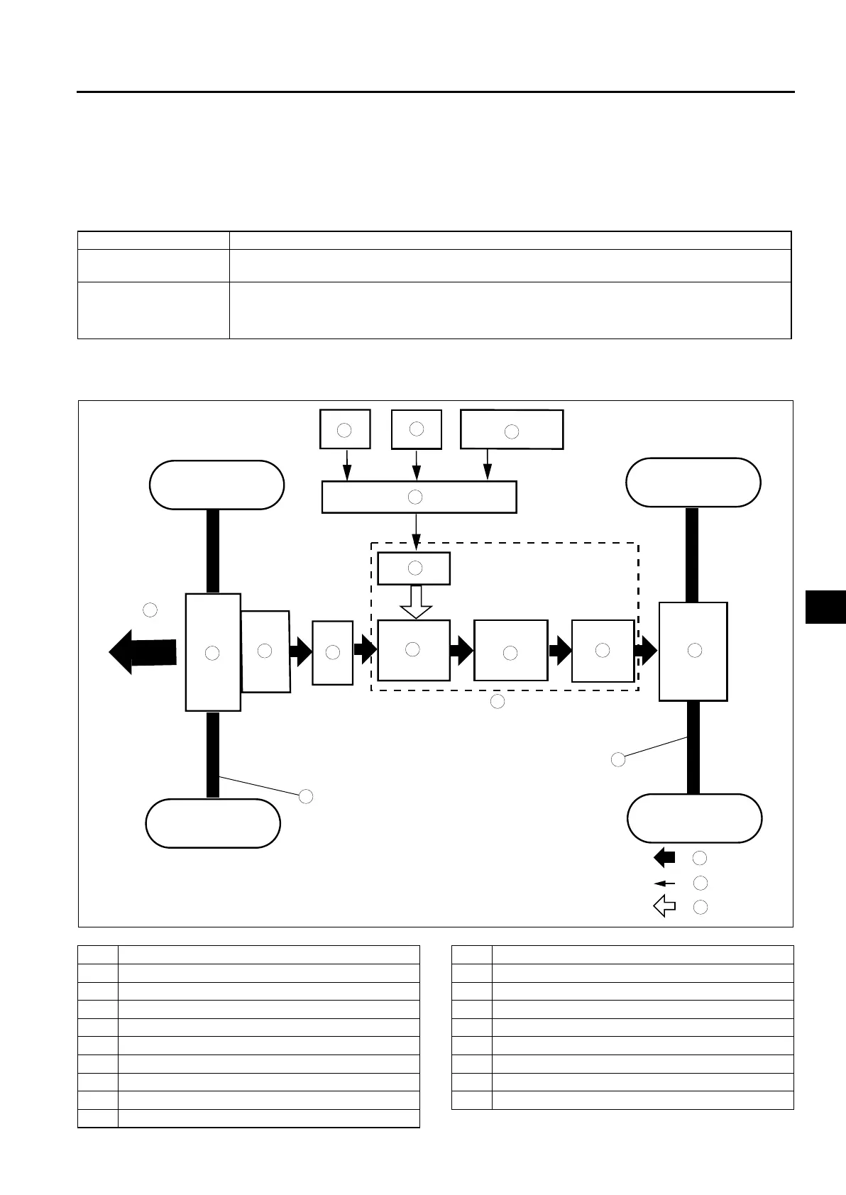
Block diagram
.
Function name Contents
4WD system control
function
• Based on each input signal, the electronic control current sent to the electronic control coupling
(4WD solenoid) is optimally controlled.
Diagnostic system
• If the self-diagnostic system detects a malfunction, the 4WD warning light illuminates to alert
the driver, and at the same time the system suspends control or performs other measures to
prevent a loss of driving stability and protect the system.
• The detected malfunction is stored as a DTC in the 4WD CM.
9
8
7
5
4
3
10
19
18
17
15
16
14
13
11
12
6
1
2
A6E63222008
1Front
2PCM
3TCM
4 DSC HU/CM
5 4WD control modure (4WD CM)
6 4WD solenoid
7Transaxle
8Transfer
9 Propeller shaft
10 Front drive shaft
11 Pilot clutch/pilot cam
12 Ball/main cam
13 Main clutch
14 Electronic control coupling
15 Rear differential
16 Rear drive shaft
17 Torque transmission path
18 Electric signal path
19 Solenoid activation