B2–6
VALVE CLEARANCE
8. Install the timing belt cover bolt as shown.
Tightening torque
7.9—10.7 N·m {80—110 kgf·cm, 69.5—95.4
in·lbf}
9. Install the engine cover. (See B2–9 TIMING BELT
REMOVAL/INSTALLATION.)
End Of Sie
VALVE CLEARANCE ADJUSTMENT
A6E231212111202
1. Remove the engine cover. (See B2–9 TIMING BELT REMOVAL/INSTALLATION.)
2. Remove the timing belt cover bolt as shown.
3. Remove the cylinder head cover. (See B2–15
CYLINDER HEAD GASKET REPLACEMENT.)
4. Turn the crankshaft clockwise and set the No.1
cylinder to compression TDC.
5. Remove the fuel injector. (See F2–55 FUEL
INJECTOR REMOVAL/INSTALLATION.)
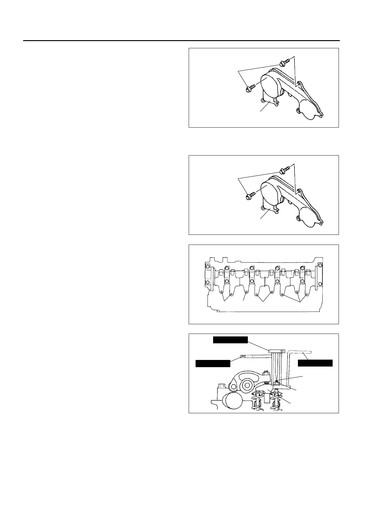
6. Adjust the valve clearance A with the No.1
cylinder at TDC of compression, and those of B
with the No.4 cylinder at TDC of compression.
(1) Hold the rocker bridge using the SST (49
G012 006).
(2) Loosen the locknut (d) using the SST (49
G012 004), and then turn the adjusting screw
(c) using the SST (49 G012 005) until it is
separated from the valve stem completely.
TIMING BELT
COVER BOLT
UPPER TIMING BELT COVER
A6E2312W200
TIMING BELT
COVER BOLT
UPPER TIMING BELT COVER
A6E2312W200
A
A
B
B
A6E2312W201
49 G012 006
49 G012 005
49 G012 004
ADJUSTING
SCREW(c)
ROCKER BRIDGE
LOCKNUT(d)
NORMAL
A6E2312W202