VALVE CLEARANCE
B2–7
B2
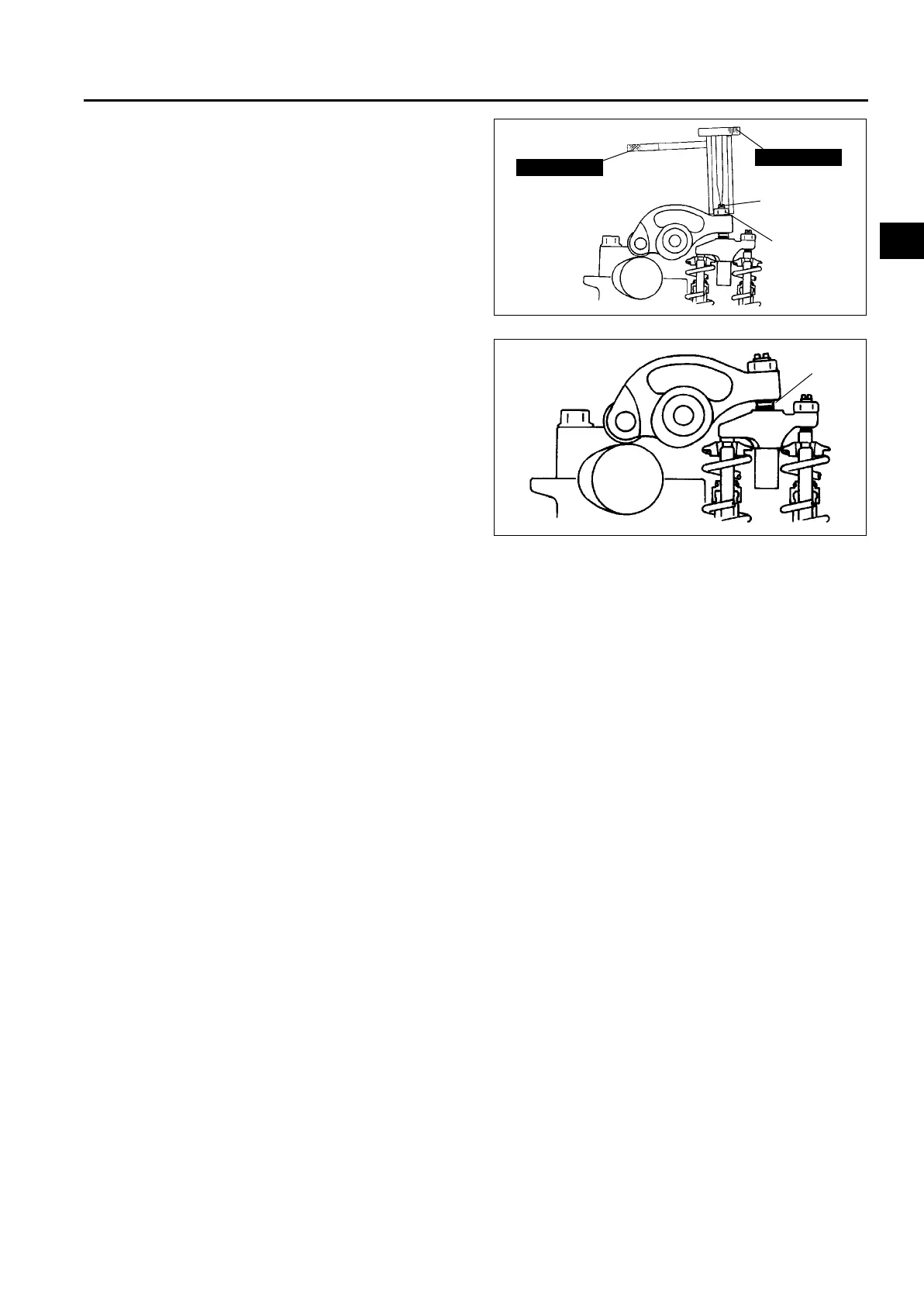
(3) Loosen the rocker arm locknut (b) using the
SST (49 G012 004), and then turn the
adjusting screw (a) using the SST (49 G012
005) until it is separated from the rocker
bridge completely.
(4) Insert a feeler gauge between the rocker arm
and rocker bridge (e).
Standard valve clearance [Engine cold]
IN: 0.12—0.18 mm {0.005—0.007 in}
(0.15±0.03 mm {0.006±0.0011 in})
EX: 0.32—0.38 mm {0.013—0.014 in}
(0.35±0.03 mm {0.014±0.0011 in})
(5) Adjust the valve clearance by turning the
adjuster (a) using the SST (49 G012 005).
Then temporarily tighten locknut (b) using the
SST (49 G012 004).
(6) With the feeler gauge inserted between the
rocker arm and rocker bridge, verify that the feeler gauge remains firmly in place even when the adjusting
screw (c) is loosened.
• If the feeler gauge does not remain firmly in place, repeat procedures from Step 1.
(7) Turn the adjusting screw (c) using the SST (49 G012 005) until it reaches the valve stem and the feeler
gauge fits more firmly. Then tighten the locknut (d) using the SST (49 G012 004) to specified torque.
Tightening torque
16—20 N·m {1.6—2.1 kgf·m, 12—15 ft·lbf}
(8) Loosen the locknut (b) using the SST (49 G012 004) and readjust the valve clearance (e).
Standard valve clearance [Engine cold]
IN: 0.12—0.18 mm {0.005—0.007 in} (0.15±0.03 mm {0.006±0.0011 in})
EX: 0.32—0.38 mm {0.013—0.014 in} (0.35± 0.03 mm {0.014±0.0011 in})
(9) Tighten the locknut (b) using the SST (49 G012 004) to specified torque.
Tightening torque
16—20 N·m {1.6—2.1 kgf·m, 12—15 ft·lbf}
(10)Verify the valve clearance at (e).
Standard valve clearance [Engine cold]
IN: 0.12—0.18 mm {0.005—0.007 in} (0.15±0.03 mm {0.006±0.0011 in})
EX: 0.32—0.38 mm {0.013—0.014 in} (0.35± 0.03 mm {0.014±0.0011 in})
7. Turn the crankshaft one full turn and adjust the remaining valve clearances.
8. Install the fuel injector. (See F2–55 FUEL INJECTOR REMOVAL/INSTALLATION.)
9. Install the cylinder head cover. (See B2–21 Cylinder Head Cover Installation Note.)
49 G012 005
49 G012 004
LOCKNUT(b)
ADJUSTING
SCREW(a)
A6E2312W203
(e)
A6E2312W204