COMPRESSION PRESSURE, TIMING BELT
B2–9
B2
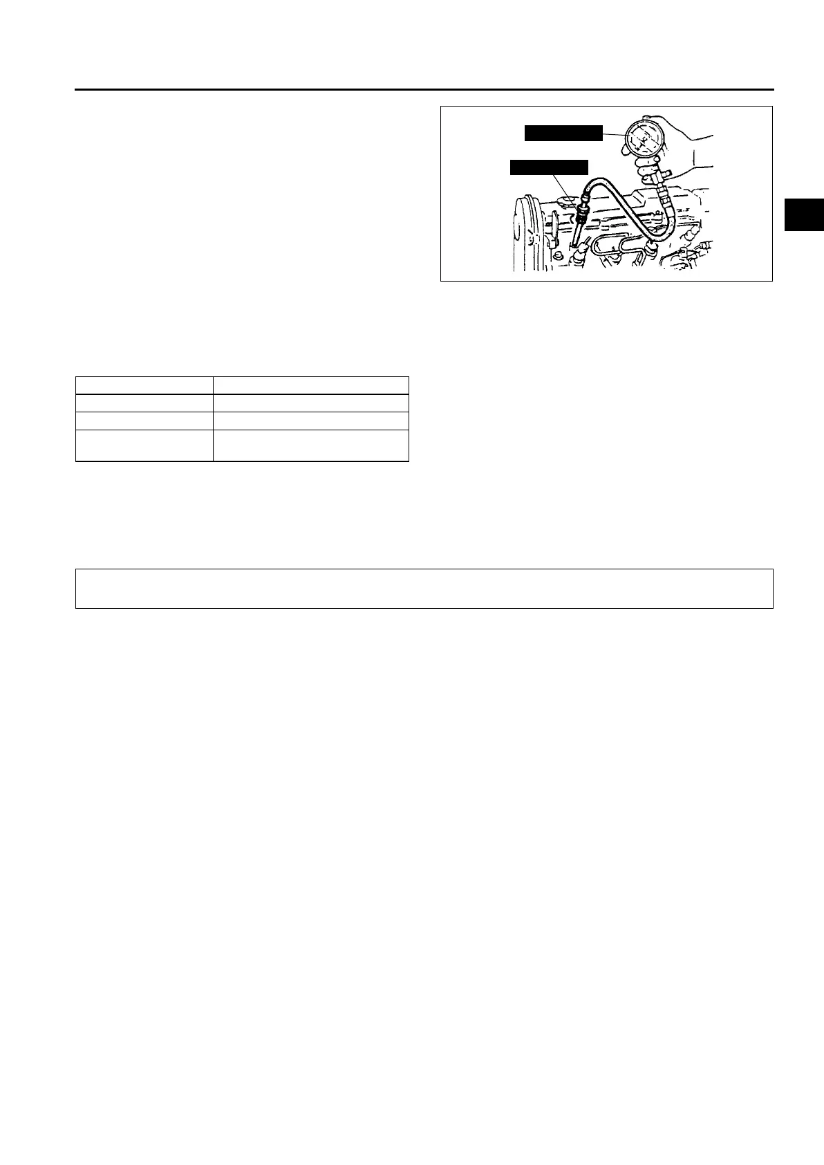
7. Install the SSTs into the glow plug hole.
8. Crank the engine and note the maximum gauge
reading.
9. Inspect each cylinder as above.
• If the compression in one or more cylinders is
low, pour a small amount of clean engine oil
into the cylinder and reinspect the
compression.
— If the compression increases, the piston,
the piston rings, or cylinder wall may be
worn and overhaul is required.
— If the compression stays low, a valve may
be stuck or improperly seated and
overhaul is required.
— If the compression in adjacent cylinders stays low, the cylinder head gasket may be damaged or the
cylinder head may be distorted and overhaul is required.
Compression
kPa {kgf/cm
2
, psi} [rpm]
10. Remove the SSTs.
11. Install the glow plug. (See F2–42 GLOW PLUG REMOVAL/INSTALLATION.)
12. Instal the engine cover. (See B2–9 TIMING BELT REMOVAL/INSTALLATION.)
13. Reconnect the fuel injector connector.
14. Erase DTC from PCM memory using the SST. (WDS or equivalent).
End Of Sie
TIMING BELT REMOVAL/INSTALLATION
A6E231612040201
Warning
• Fuel vapor is hazardous. It can very easily ignite, causing serious injury and damage. Always keep
sparks and flames away from fuel.
• Fuel line spills and leakage are dangerous. Fuel can ignite and cause serious injures or death and
damage. Fuel can also irritate skin and eyes. To prevent this, always complete the “Fuel Line
Safety Procedure”. (See F2–45 Fuel Line Safety Procedures.)
1. Disconnect the negative battery cable.
2. Remove the front tire (RH).
3. Remove the splash shield (RH).
4. Remove the washer tank.
5. Remove the drive belt. (See B2–4 DRIVE BELT REPLACEMENT.)
6. Remove the fuel filter with the fuel hose still connected and position the fuel filter so that it is out of the way.
( L.H.D.) (See F2–50 FUEL FILTER COMPONENT REMOVAL/INSTALLATION.)
7. Remove in the order shown in the table.
8. Install in the reverse order of removal.
9. Start the engine and inspect the pulleys and the drive belt for runout and contact.
Item Specification
Standard 3,500 {35.7, 507.7} [250]
Minimum 3,100 {31.6, 449.4} [250]
Maximum difference
between cylinders
196.1 {1.999, 28.44}
49 S010 1A0
49 S013 102
A6E2314W101
TIMING BELT