CONVENTIONAL BRAKE SYSTEM
P–11
P
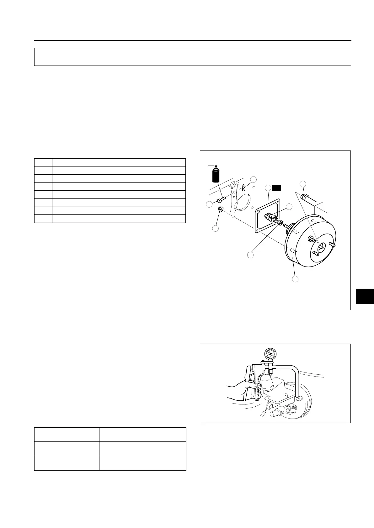
POWER BRAKE UNIT REMOVAL/INSTALLATION
A6E691243800201
1. Remove the master cylinder.
2. Remove the wiper arm.
3. Remove the cowl grille.
4. Remove the wiper motor.
5. Remove the cowl panel.
6. For L.H.D. and R.H.D. (MZR-CD (RF Turbo) only), remove the A/C bracket.
7. For L.H.D., remove the ABS (ABS/TCS) HU/CM or DSC HU/CM.
8. For R.H.D. (except MZR-CD (RF Turbo)), remove the alternator cover.
9. For R.H.D. (except MZR-CD (RF Turbo)), remove the insulator.
10. For R.H.D. (except MZR-CD (RF Turbo)), remove the vacuum pipe bracket.
11. Remove in the order indicated in the table.
12. Install in the reverse order of removal.
End Of Sie
VACUUM SWITCH INSPECTION (MZR-CD (RF TURBO))
A6E691266390201
1. Remove the vacuum hose from the power brake unit.
2. Set the vacuum pump (any commercially
available model) onto the power brake unit as
shown.
3. Turn the ignition switch to ON.
4. Release the parking brake.
5. Apply vacuum to the power brake unit using the
vacuum pump (any commercially available
model) and verify the operating condition of the
brake warning light. The vacuum switch is
functioning normally if it corresponds to the above
specifications.
• If not as specified, replace the vacuum switch.
End Of Sie
CONVENTIONAL BRAKE SYSTEM
1 Vacuum hose
2 Snap pin
3Clevis pin
4Nut
5Fork
6 Power brake unit
7Gasket
8Nut
GREASE
R
3
4
8
6
2
7
5
1
18.6—25.5
{1.90—2.60, 13.8—18.8}
N·m {kgf·m, ft·lbf}
15.7—21.6
{1.60—2.20,
11.6—15.9}
A6E6912W044
Vacuum
kPa {mm Hg, inHg}
Brake warning light
Below 10.7±2.7
{80±20, 3.1±0.8}
ON
Above 10.7±2.7
{80±20, 3.1±0.8}
OFF
A6E6912W204