F2–70
CONTROL SYSTEM
IDLE SWITCH INSPECTION
A6E404041600201
Note
• Perform the following test only when directed.
1. Verify that the accelerator position sensor is normal.
2. Visually inspect all accelerator pedal components for looseness.
3. Verify that the idle switch is installed to the accelerator pedal properly.
4. Verify that the power circuit voltage.
(1) Verify that the voltage between the PCM terminals 90 (power circuit) and 91(GND circuit) is 4.75—5.25 V.
Note
• Voltage at the PCM terminal 10 may deviate when the power circuit voltage is abnormal.
5. Verify that the voltage at the PCM terminal 31
(idle signal) is 1 V or less with the accelerator
pedal fully released.
6. Depress the accelerator pedal gradually and hold
the pedal when the PCM terminal 31 voltage
changes to approximately 10 V.
7. Verify that the voltage between the PCM
terminals 10 (accelerator position detection
signal) and 91 is within the specification.
• If the circuit is okay, replace the idle switch.
Specification
0.85—1.15 V (Target value: 1.0 V)
Circuit Open/Short Inspection
1. Inspect for open/short circuit in the following
wiring harnesses.
• If there is open/short circuit, repair or replace
wiring harnesses.
Open circuit
• Signal circuit
— Idle switch terminal A and PCM terminal 31
• GND circuit
— Idle switch terminal B and GND
Short circuit
• Signal circuit
— Idle switch terminal A and PCM terminal 31 to
GND
End Of Sie
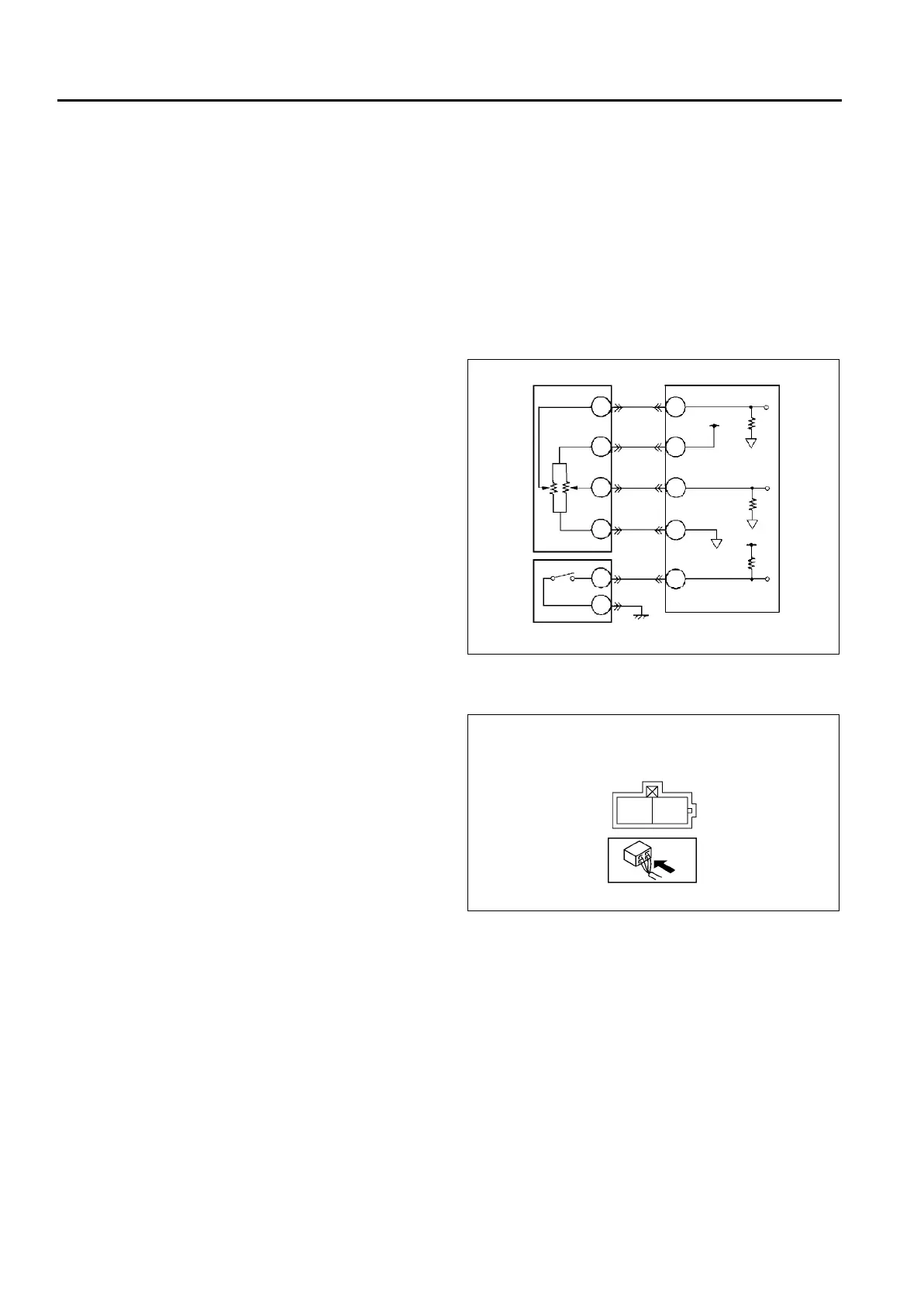
ACCELERATOR POSITION SENSOR
IDLE SWITCH
PCM
B
A
C
D
A
B
31
10
90
88
91
A6E40702037
IDLE SWITCH
HARNESS SIDE CONNECTOR
A
B
A6E40702038