B2–32
ENGINE
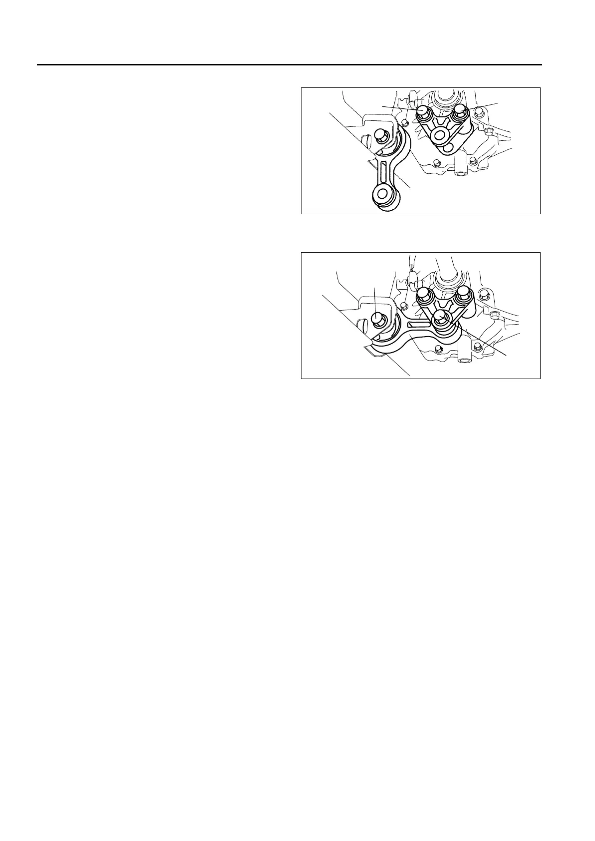
No.1 Engine Mount Bracket Installation Note
1. Tighten No.1 engine mount bracket bolt A.
Tightening torque
93.1—116.6 N·m {9.5—11.8 kgf·m,
68.7—85.9 ft·lbf}
2. Tighten No.1 engine mount bracket bolt B.
Tightening torque
93.1—116.6 N·m {9.5—11.8 kgf·m,
68.7—85.9 ft·lbf}
No.1 Engine Mount Rubber Installation Note
1. Tighten through-bolt A on the No.1 engine mount
bracket.
Tightening torque
85.3—116.6 N·m {8.7—11.8 kgf·m,
62.9—85.9 ft·lbf}
2. Tighten through-bolt B on the front crossmember
side.
Tightening torque
93.1—116.6 N·m {9.5—11.8 kgf·m,
68.7—85.9 ft·lbf}
End Of Sie
ENGINE DISASSEMBLY/ASSEMBLY
A6E232401001202
1. Disconnect the engine and transaxle. (See J2–7 MANUAL TRANSAXLE REMOVAL/INSTALLATION.)
2. Remove the intake-air system. (See F2–36 INTAKE-AIR SYSTEM REMOVAL/INSTALLATION.)
3. Remove the exhaust system. (See F2–57 EXHAUST SYSTEM REMOVAL/INSTALLATION.)
4. Remove the generator. (See G–7 GENERATOR REMOVAL/INSTALLATION.)
5. Remove the clutch. (See H–5 CLUTCH UNIT REMOVAL/INSTALLATION (A65M-R manual transaxle
models).)
6. Remove the vacuum pump. (See P–13 VACUUM PUMP REMOVAL/INSTALLATION (MZR-CD (RF
TURBO)).)
7. Remove the P/S oil pump. (See N–16 POWER STEERING OIL PUMP (MZR-CD (RF Turbo)) REMOVAL/
INSTALLATION.)
8. Disassemble in the order indicated in the table.
9. Assemble in the reverse order of disassembly.
A
B
A6E2324W207
A
B
A6E2324W201