DRIVE BELT, VALVE CLEARANCE
B2–5
B2
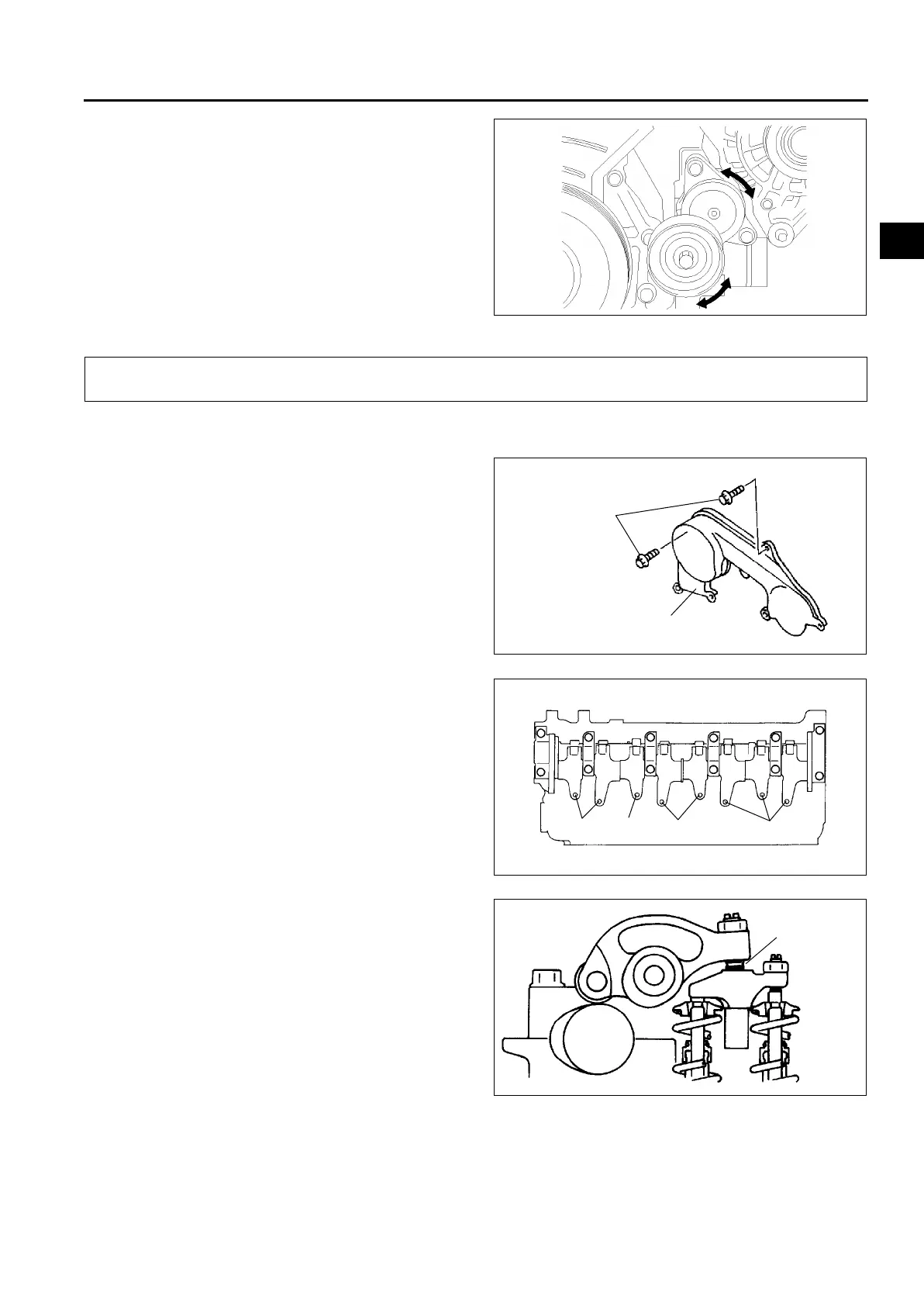
3. Turn the drive belt auto tensioner pulley by hand
and verify that it rotates smoothly.
• Replace the drive belt auto tensioner if
necessary.
4. Install the drive belt.
End Of Sie
VALVE CLEARANCE INSPECTION
A6E231212111201
1. Remove the engine cover. (See B2–9 TIMING BELT REMOVAL/INSTALLATION.)
2. Remove the timing belt cover bolt as shown.
3. Remove the cylinder head cover. (See B2–15
CYLINDER HEAD GASKET REPLACEMENT.)
4. Turn the crankshaft and align the timing mark so
that the piston of the No.1 or No.4 cylinder is at
TDC of compression.
5. Measure valve clearances A with the No.1
cylinder at TDC of compression, and those of B
with the No.4 cylinder at TDC of compression.
• If the valve clearance is not within the
specification, adjust the valves. (See B2–6
VALVE CLEARANCE ADJUSTMENT.)
Standard valve clearance [Engine cold]
IN: 0.12—0.18 mm {0.005—0.007 in}
(0.15±0.03 mm {0.006±0.0011 in})
EX: 0.32—0.38 mm {0.013—0.014 in}
(0.35±0.03 mm {0.014±0.0011 in})
6. Turn the crankshaft one full turn and measure the
remaining valve clearances.
• Adjust if necessary. (See B2–6 VALVE
CLEARANCE ADJUSTMENT.)
7. Install the cylinder head cover. (See B2–21 Cylinder Head Cover Installation Note.)
A6E2310W103
VALVE CLEARANCE
TIMING BELT
COVER BOLT
UPPER TIMING BELT COVER
A6E2312W200
A
A
B
B
A6E2312W201
MEASURING
POINT
A6E2312W101