F2–4
OUTLINE
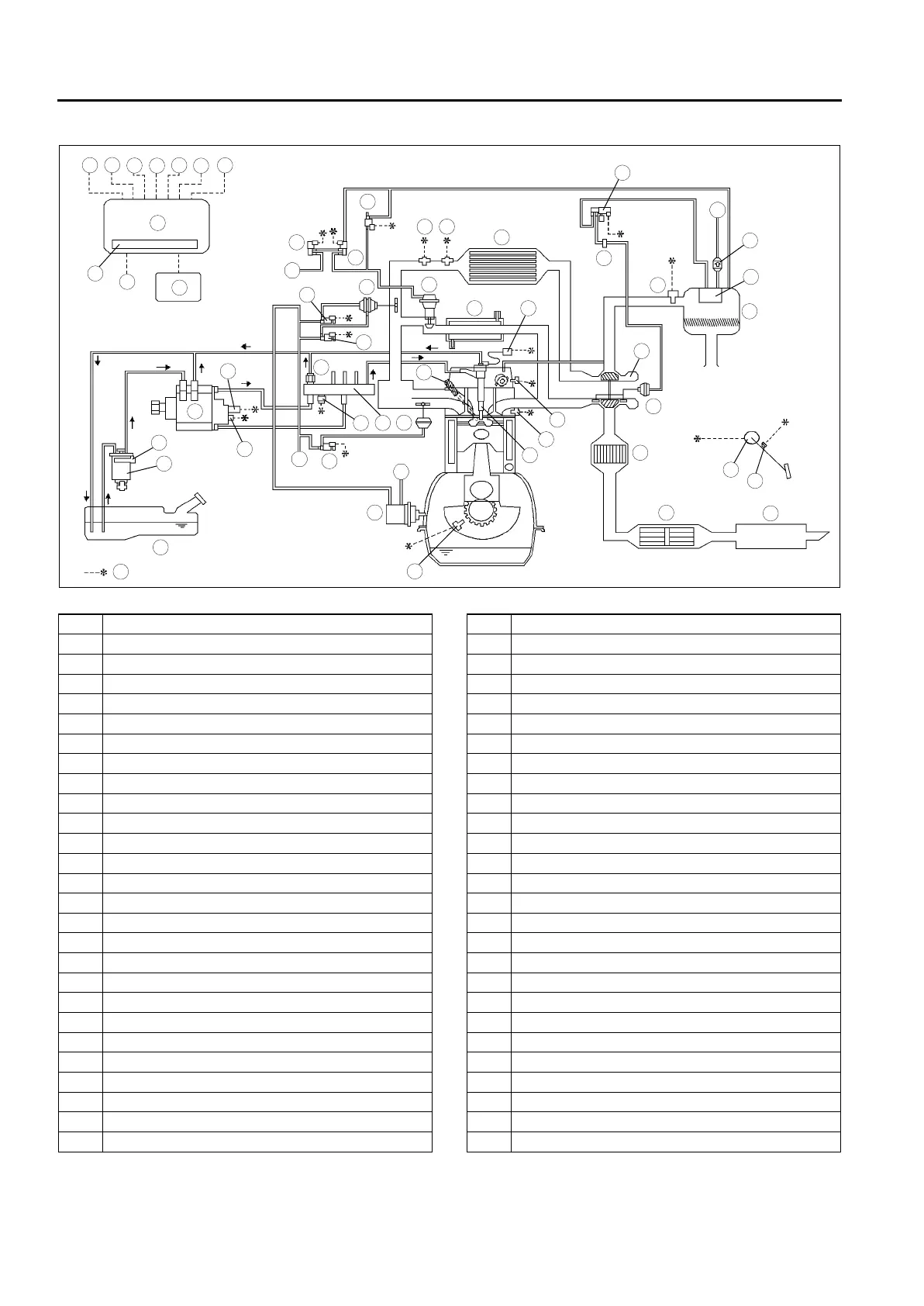
CONTROL SYSTEM DIAGRAM
A6E400218881204
.
End Of Sie
5
4
3
6
1
2
8
7
9
10
13
11
12
19
18
17
15
16
14
20
29
28
27
25
26
24
23
21
22
30
39
38
37
35
36
33
31
32
40
34
49
48
47
45
46
44
43
41
42
50
54
51
52
53
A
A
B
B
A6E40022001
1 Air cleaner
2 Vacuum chamber
3 VBC check valve
4 MAF/IAT sensor
5 VBC solenoid valve
6 Vacuum damper
7 Guide blade actuator
8 Turbocharger
9 Charge air cooler
10 IAT sensor No.2
11 Boost sensor
12 Intake shutter valve actuator
13 Intake shutter solenoid valve (half)
14 Intake shutter solenoid valve (full)
15 EGR solenoid valve (vacuum)
16 EGR solenoid valve (vent)
17 EGR control solenoid valve
18 EGR valve
19 EGR water cooler
20 VSC valve actuator
21 VSC solenoid valve
22 Fuel tank
23 Fuel filter
24 Fuel warmer
25 Supply pump
26 Suction control valve
27 Fuel temperature sensor
28 Common rail
29 Fuel pressure sensor
30 Fuel pressure limiter
31 Glow plug
32 Fuel injector
33 ECT sensor
34 Calibration resistor
35 CMP sensor
36 Warm up oxidation catalytic converter
37 Oxidation catalytic converter
38 Silencer
39 Vacuum pump
40 CKP sensor
41 Idle switch
42 Accelerator position sensor
43 Glow plug relay
44 IDM
45 PCM
46 BARO sensor
47 PCM control relay
48 Engine switch
49 Starter (starter signal)
50 Neutral switch
51 Clutch switch
52 A/C switch
53 CAN bus
54 To PCM







 To Next Page