J2–12
SHIFT MECHANISM
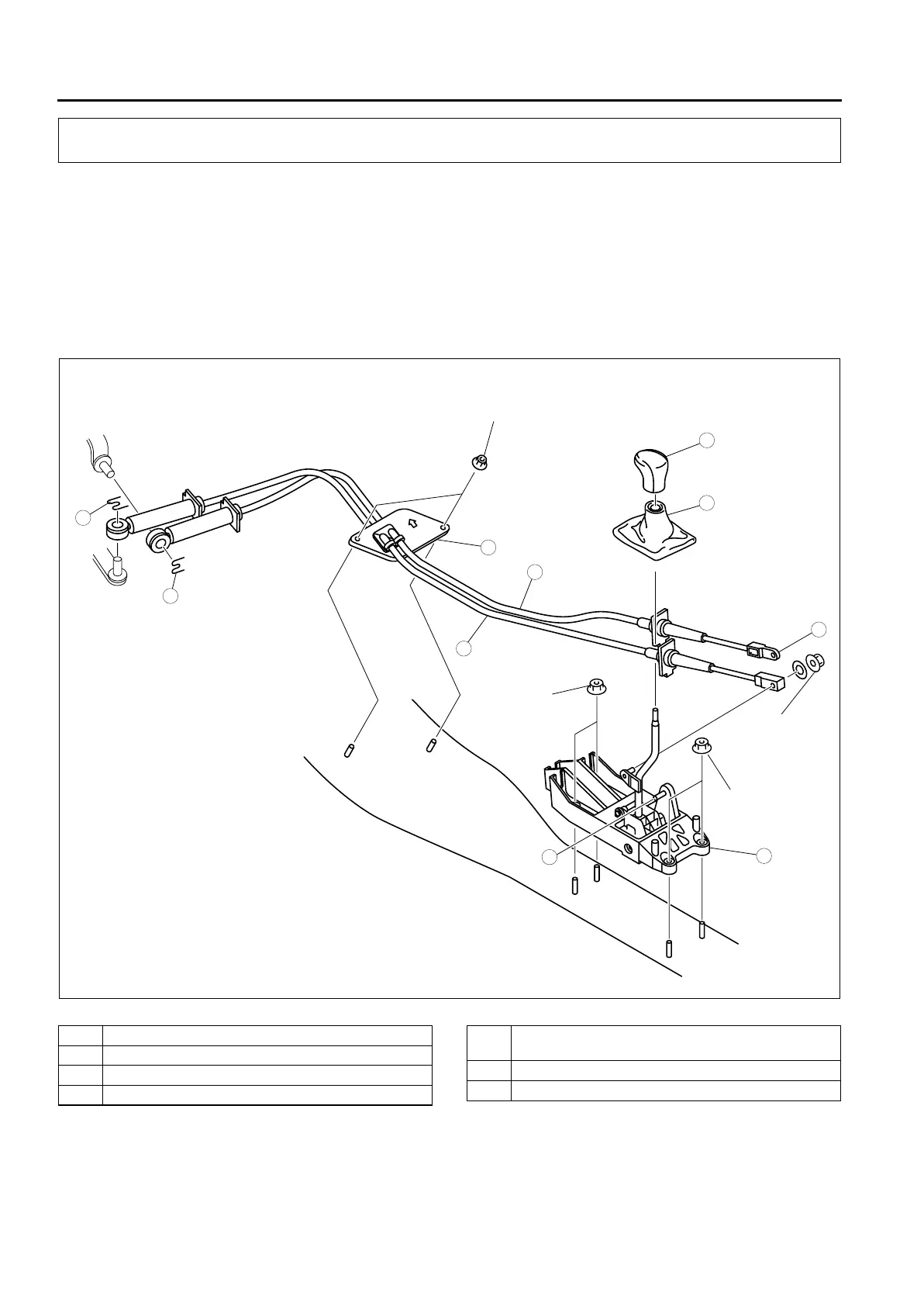
SHIFT MECHANISM REMOVAL/INSTALLATION
A6E521446010201
1. Remove the battery and battery tray.
2. Remove the air cleaner component. (See F2–36 INTAKE-AIR SYSTEM REMOVAL/INSTALLATION.)
3. Remove the dashboard compleat. (See Section S.)
4. Remove the SAS control module. (See Section T.)
5. Remove the climate control unit. (See Section U.)
6. Remove the rear heat duct. (See Section U.)
7. Remove in the order indicated in the table.
8. Install in the reverse order of removal.
9. After installation, verify that the shift lever can be shifted smoothly into each position.
.
SHIFT MECHANISM
7
5
A
A
4
3
3
6
6.86—9.8
{70—99 kgf·cm, 61—85 in·lbf}
15.68—22.54
{1.599—2.298,
11.57—16.62}
7.8—10.8
{80—110 kgf·cm,
69.5—95.4 in·lbf}
1
2
N·m {kgf·m, ft·lbf}
15.68—22.54
{1.599—2.298,
11.57—16.62}
A6E5214W001
1 Shift lever knob
2 Boot panel
3 Clip
4 Seal plate
5 Select cable
(See J2–13 Select Cable Installation Note)
6 Shift cable
7 Sift lever component












 To Next Page