F2–46
FUEL SYSTEM
1. Verify that vehicle is level.
2. Complete the “BEFORE REPAIR PROCEDURE”. (See F2–45 BEFORE REPAIR PROCEDURE.)
3. Disconnect the negative battery cable.
4. Remove the rear seat cushion.
5. Remove the service hole cover.
6. Remove the plastic fuel hose from the fuel gauge sender unit. (See F2–47 Plastic Fuel Hose Removal Note.)
(See F2–48 Plastic Fuel Hose Installation Note.)
7. Remove the fuel gauge sender unit connector.
8. Remove the fuel tank gauge cap. (See F2–47 Fuel Tank Gauge Cap Removal Note.)
9. Remove the fuel gauge sender unit. (See F2–48 Fuel Gauge Sender Unit Installation Note.)
10. Siphon the fuel from the fuel tank.
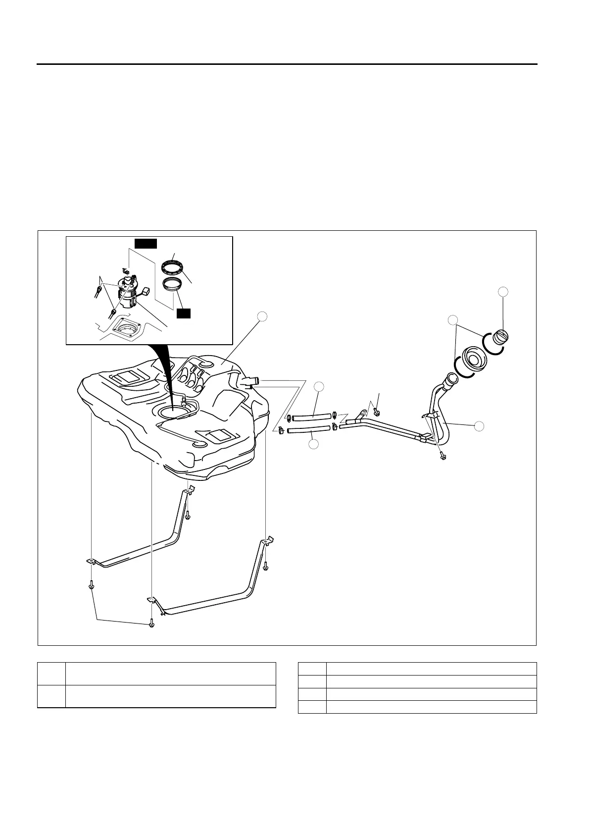
11. Remove in the order indicated in the table.
12. Install in the reverse order of removal.
13. Complete the “AFTER REPAIR PROCEDURE”. (See F2–45 AFTER REPAIR PROCEDURE.)
.
44—60
{4.4—6.2, 32—44}
44—60
{4.4—6.2, 32—44}
44—60
{4.4—6.2, 32—44}
N·m {kgf·m, ft·lbf}
8.9—12.7 N·m
{90—130 kgf·cm,
79—112 in·lbf}
8.9—12.7 N·m
{90—130 kgf·cm,
79—112 in·lbf}
5
4
3
2
1
6
80—90
{8.2—9.1, 59—66}
R
PLASTIC
FUEL HOSE
FUEL GAUGE
SENDER UNIT
FUEL TANK
GAUGE CAP
SST
A6E40122025
1
Joint hose
(See F2–48 Joint Hose Installation Note)
2
Breather hose
(See F2–48 Breather Hose Installation Note)
3 Fuel tank
4 Fuel-filler pipe
5 C-ring
6 Filler cap












 To Next Page