CONTROL SYSTEM
F2–67
F2
Not Using WDS or Equivalent
Constant voltage terminal inspection
1. Turn the engine switch to ON.
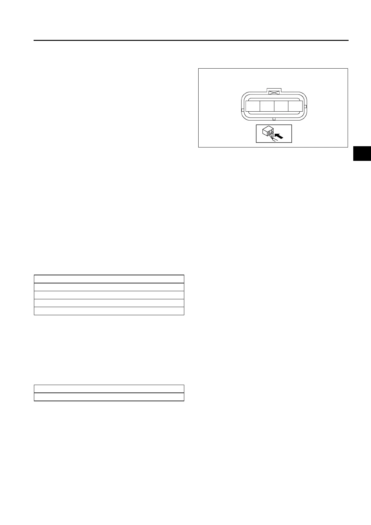
2. Measure the voltage between the accelerator
position sensor terminal A (vehicle side) and body
GND using a voltmeter.
(1) Measurement voltage is below 1.0 V.
1)
Turn the engine switch to OFF.
2)
Disconnect the accelerator position
sensor connector.
3)
Verify there is no continuity between the
accelerator position sensor terminal A
(vehicle side) and body GND using an
ohmmeter.
• If there is continuity, repair or replace
the related harness.
4)
Inspect for continuity between the PCM
terminal 90 (vehicle side) and accelerator position sensor terminal A (vehicle side) using an ohmmeter.
• If there is no continuity, repair or replace the related harness.
(2) Measurement voltage is B+.
1)
Turn the engine switch to OFF.
2)
Disconnect the battery negative cable and battery positive cable.
3)
Verify there is no continuity between the accelerator position sensor terminal A (vehicle side) and
battery positive cable using an ohmmeter.
• If there is continuity, repair or replace the related harness.
(3) Measurement voltage is approx. 5 V.
• Constant voltage terminal of PCM is okay.
GND terminal inspection
1. Turn the engine switch to OFF.
2. Disconnect the PCM connector.
3. Inspect for continuity between the PCM GND terminals and body GND using an ohmmeter.
• If there is no continuity, repair or replace the related harness.
Power supply terminal inspection
1. Disconnect the PCM connector.
2. Turn the engine switch to ON.
3. Measure the voltage between the PCM battery power terminal and body GND using a voltmeter.
• If not as specified, repair or replace the related harness.
Specification
B+
End Of Sie
ACCELERATOR POSITION SENSOR
HARNESS SIDE CONNECTOR
A
B
C
D
A6E40702042
PCM GND terminal
65
85
103
104
PCM power supply terminal
27












 To Next Page