F2–104
ON-BOARD DIAGNOSTIC
End Of Sie
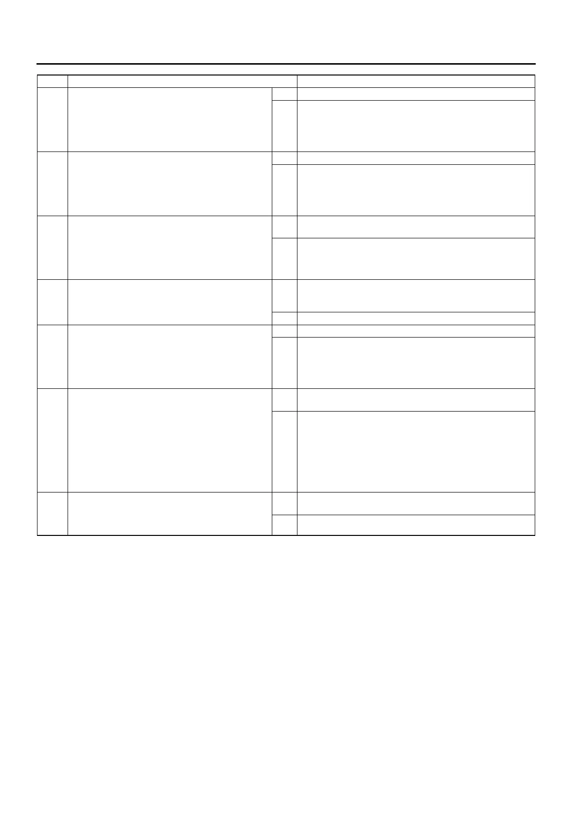
4 INSPECT BOOST SENSOR POWER CIRCUIT
FOR OPEN
• Turn engine switch to ON. (Engine OFF)
• Inspect voltage at boost sensor terminal C
(harness side).
• Is voltage below 1.0 V?
Yes Repair or replace harness for open, go to Step 9.
No Go to next step.
5 INSPECT BOOST SENSOR SIGNAL CIRCUIT
FOR SHORT TO GND
• Turn engine switch to OFF.
• Inspect continuity between boost sensor
terminal B and body GND.
• Is there continuity?
Yes Repair or replace harness for short to GND, go to Step 9.
No Go to next step.
6 INSPECT BOOST SENSOR CIRCUIT FOR
SHORT WITH EACH OTHER
• Turn engine switch to OFF.
• Inspect continuity between boost sensor
terminals B and A.
• Is there continuity?
Yes Repair or replace harness for short with each other, go to
Step 9.
No Go to next step.
7 INSPECT BOOST SENSOR
• Inspect boost sensor.
(See F2–78 BOOST SENSOR INSPECTION)
• Is there any malfunction?
Yes Replace boost sensor, go to Step 9.
(See F2–36 INTAKE-AIR SYSTEM REMOVAL/
INSTALLATION)
No Go to next step.
8 INSPECT POOR CONNECTION OF PCM
CONNECTOR
• Turn engine switch to OFF.
• Inspect for poor connection (damaged, pulled-
out terminals, corrosion, etc.).
• Is there any malfunction?
Yes Repair or replace suspected terminal, go to next step.
No Go to next step.
9 VERIFY TROUBLESHOOTING OF DTC P0107
COMPLETED
• Make sure to reconnect all disconnected
connectors.
• Clear DTC from PCM memory using WDS or
equivalent.
• Perform KOEO/KOER self-test.
(See F2–86 KOEO/KOER SELF-TEST
PROCEDURE)
• Is same DTC present?
Yes Replace PCM, go to next step.
(See F2–64 PCM REMOVAL/INSTALLATION)
No Go to next step.
10 VERIFY AFTER REPAIR PROCEDURE
• Perform “After Repair Procedure”.
(See F2–86 AFTER REPAIR PROCEDURE)
• Is there any DTC present?
Yes Go to applicable DTC inspection.
(See F2–87 DTC TABLE)
No Troubleshooting completed.
STEP INSPECTION ACTION