ON-BOARD DIAGNOSTIC
K2–167
K2
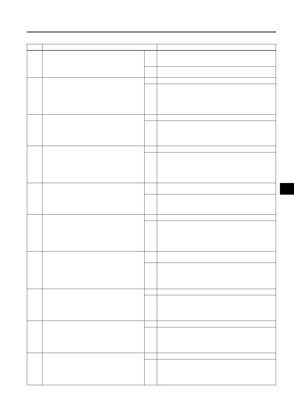
Diagnostic procedure
STEP INSPECTION ACTION
1 VERIFY RELATED REPAIR INFORMATION
AVAILABILITY
• Check for related Service Bulletins and/or on-
line repair information availability.
• Is any related repair information available?
Yes Perform repair or diagnosis according to available repair
information.
• If vehicle is not repaired, go to next step.
No Go to next step.
2 INSPECT TERMINAL COMPONENT NO.1 (12-
PIN) FOR POOR CONNECTION
• Turn ignition key to OFF.
• Disconnect terminal component No.1 (12-pin).
• Check for poor connection (damaged, pulled-
out, terminals, corrosion, etc.).
• Are terminals okay?
Yes Go to next step.
No Repair or replace terminals, then go to Step 12.
3 INSPECT RESISTANCE
• Check resistance between terminal component
No.1 (12-pin) terminal H (transaxle case side)
and body ground.
• Is resistance within 14—18 ohms?
(See K2–88 SOLENOID VALVE INSPECTION.)
Yes Go to Step 8.
No Go to next step.
4 INSPECT COUPLER COMPONENT (10-PIN)
FOR POOR CONNECTION
• Disconnect coupler component (10-pin)
connector.
• Check for poor connection (damaged, pulled-
out, terminals, corrosion, etc.).
• Is terminal okay?
Yes Go to next step.
No Repair or replace terminal, then go to Step 12.
5 INSPECT RESISTANCE
• Check resistance between coupler component
(10-pin) terminal B (part side) and body
ground.
• Is resistance within 14—18 ohms?
(See K2–88 SOLENOID VALVE INSPECTION.)
Yes Repair or replace terminal component No.1 (12-pin), then
go to Step 12.
No Go to next step.
6 INSPECT NEUTRAL SHIFT SOLENOID VALVE
CONNECTOR FOR POOR CONNECTION
• Disconnect neutral shift solenoid valve
connector.
• Check for poor connection (damaged, pulled-
out, terminals, corrosion, etc.).
• Is terminal okay?
Yes Go to next step.
No Repair or replace terminal, then go to Step 12.
7 INSPECT RESISTANCE
• Check resistance between neutral shift
solenoid valve connector terminal A (part side)
and body ground.
• Is resistance within 14—18 ohms?
(See K2–88 SOLENOID VALVE INSPECTION.)
Yes Repair or replace coupler component (10-pin), then go to
Step 12.
No Verify neutral shift solenoid valve installation.
• If neutral shift solenoid valve is installed correctly,
replace neutral shift solenoid valve, then go to Step 12
(See K2–90 SOLENOID VALVE REMOVAL/
INSTALLATION.)
8 INSPECT TCM CONNECTOR FOR POOR
CONNECTION
• Disconnect TCM connector.
• Check for poor connection (damaged, pulled-
out, terminals, corrosion, etc.).
• Are terminals okay?
Yes Go to next step.
No Repair terminals, then go to Step 12.
9 INSPECT TERMINAL COMPONENT NO.1 (12-
PIN) CIRCUIT FOR OPEN CIRCUIT
• Check continuity between TCM terminal 2D
(harness-side) and terminal component No.1
(12-pin) terminal H (harness-side).
• Is there continuity between terminals?
Yes Go to next step.
No Repair or replace harness, then go to Step 12.
10 INSPECT TERMINAL COMPONENT NO.1 (12-
PIN) CIRCUIT FOR SHORT TO POWER
• Turn ignition key to ON (engine OFF).
• Check voltage at terminal component No.1 (12-
pin) terminal H (harness-side).
• Is voltage 0 V?
Yes Go to next step.
No Repair or replace harness, then go to Step 12.












 To Next Page