K2–190
TROUBLESHOOTING
Diagnostic procedure
End Of Sie
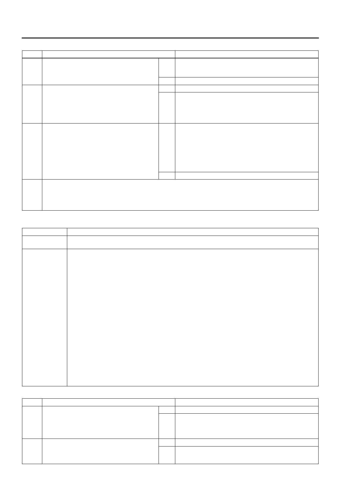
NO.6 LOW MAXIMUM SPEED AND POOR ACCELERATION
A6E578001030209
Diagnostic procedure
STEP INSPECTION ACTION
1 • Does vehicle creep in P and/or N position? Yes Inspect or adjust the selector lever.
(See K2–117 SELECTOR LEVER INSPECTION.)
(See K2–118 SELECTOR CABLE ADJUSTMENT.)
No Go to next step.
2 • Stop engine.
• Inspect pressure control solenoid circuit.
• Is it okay?
Yes Go to next step.
No • Inspect for pressure control solenoid mechanical stuck.
(See K2–88 SOLENOID VALVE INSPECTION.)
— If pressure control solenoid okay, inspect for open or
short circuit between TCM connector terminal 2Y and
pressure control solenoid connector terminal D.
3 • Remove torque converter.
• Inspect torque converter.
(See ATX Workshop Manual.)
• Is torque converter okay?
Yes • Overhaul control valve body and repair or replace any
defective parts.
(See ATX Workshop Manual.)
— If problem remains, replace or overhaul transaxle and
repair or replace any defective parts.
(See K2–99 AUTOMATIC TRANSAXLE AND
TRANSFER REMOVAL/INSTALLATION.)
(See ATX Workshop Manual.)
No Replace torque converter.
4 • Verify test results.
— If okay, return to diagnostic index to service any additional symptoms.
— If malfunction remains, inspect related Service Informations and perform repair or diagnosis.
— If vehicle repaired, troubleshooting completed.
— If vehicle not repaired or additional diagnostic information not available, replace TCM.
6 Low maximum speed and poor acceleration
DESCRIPTION
• Vehicle acceleration poor at start.
• Delayed acceleration when accelerator pedal depressed while driving.
POSSIBLE
CAUSE
• If clutch is stuck or does not stay in 4GR, malfunction is in engine circuit.
— Clutch slipped, burned
• Line pressure low
• Incorrect throttle position signal
• Malfunction of VSS
• Malfunction of input/turbine speed sensor
• Malfunction of sensor ground
• Malfunction of shift solenoids A, B, or C
• Malfunction of body ground
• Malfunction of control valve body
— Transaxle fixed in 4GR (Operation of fail-safe function)
• Short or open circuit in wiring
• Poor connection of connector
• Electronic parts of output and input system malfunction are malfunctioning
— Insufficient starting torque (Suspected when in-gear condition, shift control and engine circuit are
normal)
• Malfunction of torque converter (Poor operation, sticking)
— Engagement of TCC operation range (Operation of fail-safe function)
• Malfunction of TFT sensor (Short or open circuit)
Note
• Before following troubleshooting steps, make sure that Automatic Transaxle On-Board Diagnostic
and Automatic Transaxle Basic Inspection are conducted.
STEP INSPECTION ACTION
1 • With ignition switch at ON, does gear
position indicator light indication correspond
to selector lever position?
Yes Go to next step.
No Go to symptom troubleshooting No.27 “Gear position
indicator light does not illuminate in M range”, or No.28
“Gear position indicator light illuminates in D range or P, N,
R position”.
2 • Go to symptom troubleshooting No.12 “Lack/
loss of power-acceleration/cruise”.
(See Section F.)
• Does engine control system okay?
Yes Go to next step.
No Repair or replace any defective parts according to
inspection results.












 To Next Page