M–8
ELECTRONIC 4WD CONTROL SYSTEM
Components and Functions
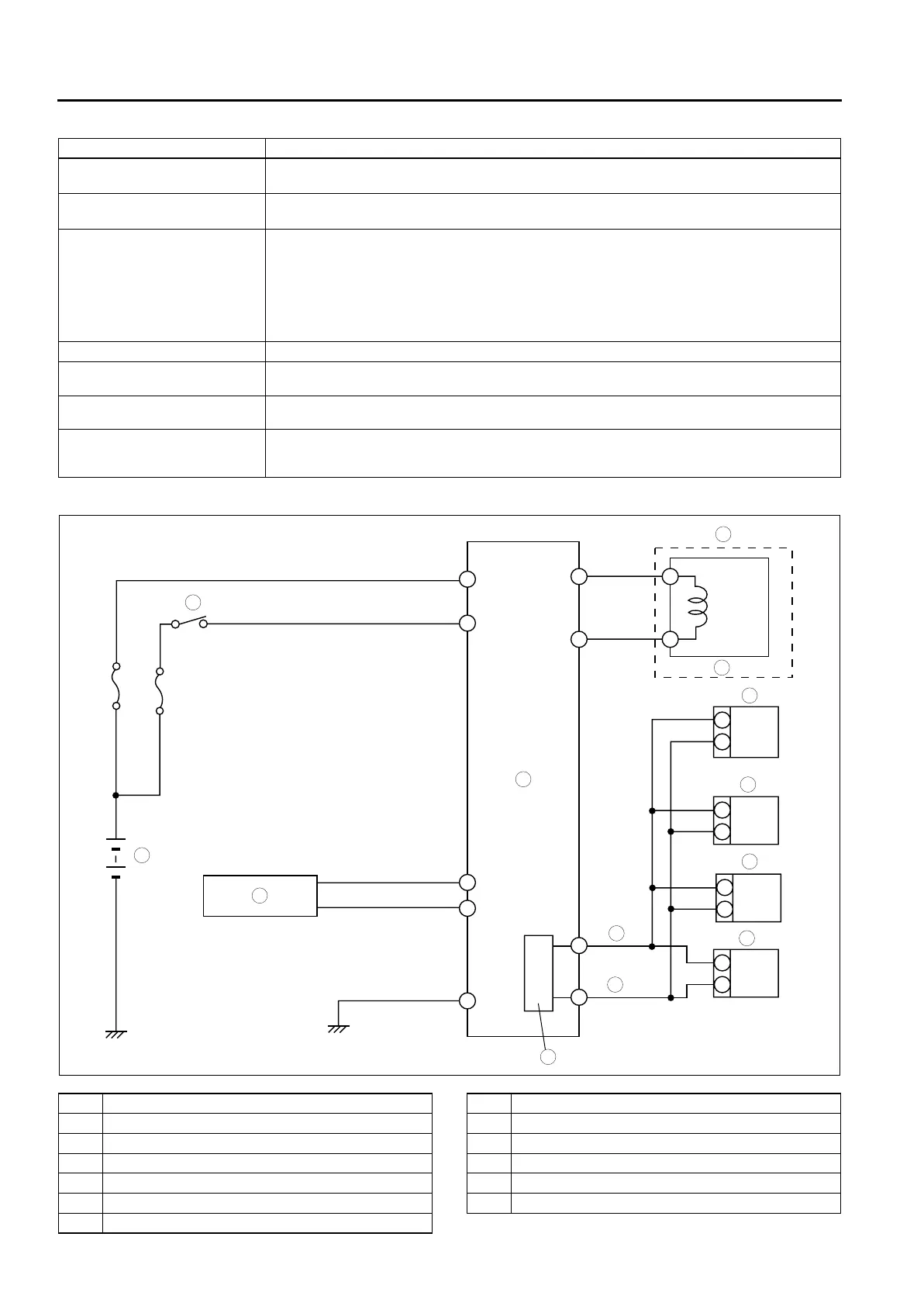
System Diagram
.
Part name Function
Electronic control coupling
(4WD solenoid)
• Based on a signal from the 4WD CM, it operates the electromagnetic clutch and
transmits drive torque to the rear wheels.
Differential oil temperature
sensor
• Informs the 4WD CM of the rear differential oil temperature.
4WD CM
• Controls operation of the electronic control coupling (4WD solenoid) based on signals
input from the throttle opening angle, speed, differential oil temperature and other
sensors.
• Outputs coupling control condition and 4WD warning control information as a CAN
signal.
• Controls the on-board diagnostic system and the fail-safe system if there is a malfunction
in the 4WD system.
4WD warning light • Illuminates or flashes to alert driver of a malfunction or control failure in the 4WD system.
PCM
• Sends the throttle opening angle and engine speed signals, as CAN signals, to the 4WD
CM.
TCM
• Sends the selector lever position and gear position signals, as CAN signals, to the 4WD
CM.
DSC HU/CM
• Sends the four-wheel speed and DSC operating condition signals, as CAN signals, to the
4WD CM.
• Sends the coupling torque request signal, as a CAN signal, to the 4WD CM.
K
O
P
I
A
C
N
H
G
9
8
7
5
4
3
10
13
11
12
6
1
2
A6E63222002
1 Battery
2 Ignition switch
3 Differential oil temperature sensor
4 4WD control modure (4WD CM)
5 Electronic control coupling
6 4WD solenoid
7 Instrument cluster
8 DSC HU/CM
9TCM
10 PCM
11 CAN-H
12 CAN-L
13 CAN driver












 To Next Page